
BOSCH REXROTH
R900912561
$514.00 USD
- BOSCH REXROTH
- Material:R900912561
- Model:LC25DR40E7X/
Due to extremely high demand, please call 920-337-0234 for availability
The Bosch Rexroth LC25DR40E7X/ (R900912561) is a high-performance, hydraulically actuated industrial hydraulic valve designed for reliable pressure reduction to a preset value. This model features a spool valve with a pilot-operated mechanism and a spool symbol B A, indicating its functionality for directing flow from port B to port A. With a maximum pressure rating suitable for demanding applications, the LC25DR40E7X/ is classified under Productgroup ID and includes multiple ports of Size B. This valve boasts an impressive maximum flow rate and utilizes a cartridge valve type of connection that conforms to the ISO standard. The connection diagram adheres to ISO specifications, ensuring compatibility with standardized systems. The number of switching positions and weight of the valve are optimized for its size category. Equipped with NBR seals, the LC25DR40E7X/ is compatible with various hydraulic fluids including HL, HLP, HLPD, HVLP, HVLPD, and HFC. Its way cartridge valves for pressure functions are designed as pilot-operated valves in both seat or spool designs. The power section is crafted as a cartridge valve that fits into receiving holes standardized according to DIN ISO standards. The integrated pilot control valve enables manual or electrically proportional pressure adjustment and can be installed on the control cover as per DIN standards. By combining these cartridge valves with different control covers, various pressure functions can be achieved. For its pressure reducing function, the valve remains open in its rest position. The design ensures no effective areas at port B, making it efficient in operation. When the set pressure is reached, the spool closes to reduce pressure at port A according to preset characteristics. Overall, the Bosch Rexroth LC25DR40E7X/ (R900912561) offers robust performance for industrial applications requiring precise pressure reduction capabilities within hydraulic systems.
Size 25, B → A, hydraulically actuated
Industrial hydraulic valve in a high performance range. Reliable pressure reduction to setting value.
Unpacked Weight: 0.46 kg
General
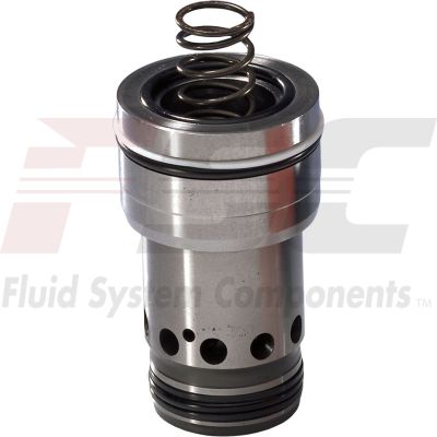
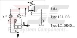
2-way cartridge valves for pressure functions are pilot-operated valves in seat or spool design. The power section designed as cartridge valve (1) is installed into a receiving hole standardized according to DIN ISO 7368 and closed with a control cover (2).
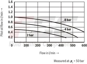
The pilot control valve (4) for manual or electrically proportional pressure adjustment is integrated into the control cover (2) or is installed on the control cover (2) as pilot valve with mounting dimensions according to DIN 24 340.
By combination of cartridge valves with the control covers, different pressure functions can be realized. .
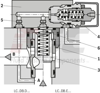
Pressure reducing function
Rest position open
The cartridge valve for the pressure reducing function is designed as spool valve without area difference (no effective areas at port B).
As pilot control valve, identical cover types as for the pressure relief function are applied (type LFA..DB...).
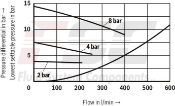
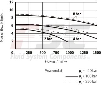
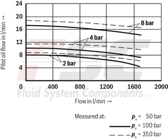
The effective pressure at port A is directed via the pilot oil supply orifice to the spring side of the spool. Under the performance limit and the pressure set at the pilot control valve, the spool is pressure-compensated and retained in open position by the spring force to enable free flow from port B to port A.
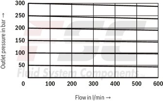
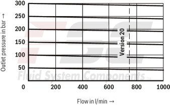
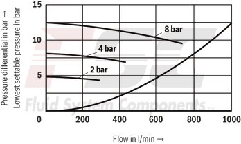
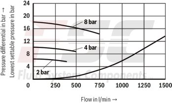
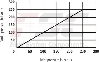
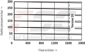
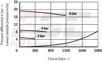
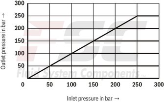
On reaching the set pressure, the spool is closed and the pressure at port A is reduced according to the pressure-flow characteristics.
| Spool valve |
| Pilot-operated |
| Data Sheet | Download Data Sheet |
| Manual | Download Manual |
| Manual | Download Manual |
| Manual | Download Manual |
| Manual | Download Manual |
| Manual | Download Manual |
| Spool symbol | B → A |
| Max. pressure | 315 |
| Productgroup ID | 9,10,11,12,13,14 |
| Number of ports | 2 |
| Type of actuation | with hydraulic actuation |
| Size | 25 |
| Max. flow | 450 |
| Type of connection | Cartridge valve |
| Connection diagram | ISO 7368-08-3-1-16 |
| Number of switching positions | 2 |
| Weight | 0.46 |
| Seals | NBR |
| Hydraulic fluid | HL,HLP,HLPD,HVLP,HVLPD,HFC |
|
Type |
||
|
01 |
Cartridge valve |
LC |
|
Size |
||
|
02 |
NG 16 |
16 |
|
NG 25 |
25 |
|
|
NG 32 |
32 |
|
|
NG 40 |
40 |
|
|
NG 50 |
50 |
|
|
NG 63 |
63 |
|
|
Version |
||
|
03 |
Pressure relief function |
DR |
|
Cracking pressure |
||
|
04 |
Cracking pressure 0 bar (without spring) |
00 |
|
Cracking pressure approx. 2 bar |
20 |
|
|
Cracking pressure approx. 3 bar 1) |
30 |
|
|
Cracking pressure approx. 4 bar |
40 |
|
|
Cracking pressure approx. 5 bar (NG16, 25 and 32 only) |
50 |
|
|
Cracking pressure approx. 8 bar 2) |
80 |
|
|
Damping |
||
|
05 |
Piston without precision grooves |
E |
|
Component series |
||
|
06 |
Component series 70 ... 79 (70 ... 79: unchanged installation and connection dimensions) |
7X |
|
Seal material |
||
|
07 |
NBR seals |
no code |
|
FKM seals |
V |
|
|
01 |
02 |
03 |
04 |
05 |
06 |
07 |
|
|
LC |
DR |
E |
7X |
/ |
Additional preferred types and standard units are specified in the EPS (standard price list).
|
Hydraulic fluid |
Classification |
Suitable sealing materials |
Standards |
|
|
Mineral oil |
HL, HLP |
FKM, NBR |
DIN 51524 |
|
|
Bio-degradable |
Insoluble in water |
HEES (synthetic esters) |
FKM |
VDMA 24568 |
|
HETG (rape seed oil) |
FKM, NBR |
|||
|
Soluble in water |
HEPG (polyglycols) |
FKM |
VDMA 24568 |
|
|
Other hydraulic fluids on request |
||||
hydraulic
|
Size |
16 | 25 | 32 | 40 | 50 | 63 | ||
|
Maximum operating pressure |
Port A |
bar |
315 | |||||
|
Port B |
bar |
315 | ||||||
|
Maximum flow |
LC..DR20.../.. |
l/min |
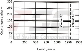
100 | 200 | 300 | 750 | 1000 | 1600 |
|
LC..DR40.../.. |
l/min |
150 | 300 | 450 | 1000 | 1300 | 2000 | |
|
Hydraulic fluid |
Mineral oil (HL, HLP) according to DIN 51524; fast biodegradable hydraulic fluids according to VDMA 24568 ; HETG (rape seed oil); HEPG (polyglycols); HEES (synthetic esters), other hydraulic fluids on request | |||||||
|
Hydraulic fluid temperature range |
NBR seals |
°C |
-30 … +80 | |||||
|
FKM seals |
°C |
-20 … +80 | ||||||
|
Viscosity range |
mm²/s |
2.8 … 380 | ||||||
|
Maximum admissible degree of contamination of the hydraulic fluid 1) |
Class 20/18/15 according to ISO 4406 (c) | |||||||
| 1) | The cleanliness classes specified for the components must be adhered to in hydraulic systems. Effective filtration prevents faults and simultaneously increases the life cycle of the components. For the selection of the filters, see www.boschrexroth.com/filter. |
For applications outside these parameters, please consult us!
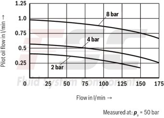
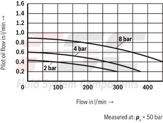
(measured with HLP46, ϑOil = 40 ±5 °C)
LC 16 DR…
LC 16 DR…
LC 16 DR…

LC 16 DR…
(measured with HLP46, ϑOil = 40 ±5 °C)
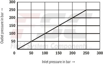
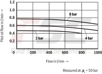
LC 25 DR…
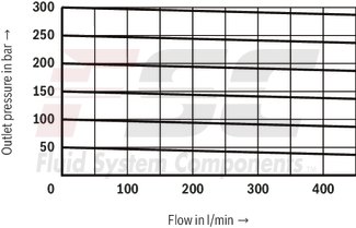
LC 25 DR…
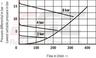
LC 25 DR…

LC 25 DR…
(measured with HLP46, ϑOil = 40 ±5 °C)
LC 32 DR…
LC 32 DR…
LC 32 DR…

LC 32 DR…
(measured with HLP46, ϑOil = 40 ±5 °C)
LC 40 DR…
LC 40 DR…
LC 40 DR…
LC 40 DR…
(measured with HLP46, ϑOil = 40 ±5 °C)
LC 50 DR…
LC 50 DR…
LC 50 DR…
LC 50 DR…
(measured with HLP46, ϑOil = 40 ±5 °C)
LC 63 DR…
LC 63 DR…
LC 63 DR…
LC 63 DR…

|
Version "E" |
Version “D” |
||
|
Area ratio |
Area ratio |
Area ratio |
Area ratio |
Installation bore and connection dimensions according to ISO 7368
Dimensions in mm
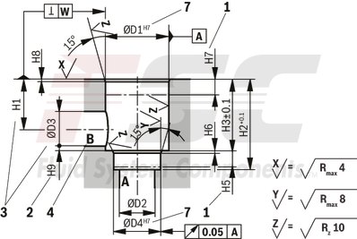
|
1 |
Depth of fit |
|
2 |
Control dimension |
|
3 |
If a different diameter is used for port B than ØD3 or (ØD3*), the distance from the cover support surface to the bore center must be calculated. |
|
4 |
Port B may be positioned around the central axis of port A. However, it must be observed that the mounting bores and the control bores are not damaged. |
|
7 |
At Ø ≤45 mm → Fitting H8 admissible |
|
NG |
ØD1 |
ØD2 |
ØD3/(ØD3*) |
ØD4 |
ØD5 |
ØD6 1) |
ØD7 |
H1/(H1*) |
H2 |
H3 |
H4 |
H5 |
H6 |
H7 |
H8 |
H9 |
L1 |
L2 |
L3 |
L4 |
L5 |
W |
|||
|
mm |
mm |
mm |
mm |
mm |
mm |
mm |
mm |
mm |
mm |
mm |
mm |
mm |
mm |
mm |
mm |
mm |
mm |
mm |
mm |
mm |
|||||
| 16 | 32 |
H7 - |
16 |
16 25 |
25 |
H7 - |
M8 | 8 | 4 |
H13 - |
35 29.5 |
56 | 43 | 20 | 11 | 2 | 20 | 2 | 0.5 |
65 80 |
46 | 23 | 25 | 10.5 | 0.05 |
| 25 | 45 |
H7 - |
25 |
25 32 |
34 |
H7 - |
M12 | 6 | 6 |
H13 - |
44 40.5 |
72 | 58 | 25 | 12 | 2.5 | 30 | 2.5 | 1 |
85 - |
58 | 29 | 33 | 16 | 0.05 |
| 32 | 60 |
H7 - |
32 |
32 40 |
45 |
H7 - |
M16 | 8 | 6 |
H13 - |
52 48 |
85 | 70 | 35 | 13 | 2.5 | 30 | 2.5 | 1.5 |
102 - |
70 | 35 | 41 | 17 | 0.1 |
| 40 | 75 |
H7 - |
40 |
40 50 |
55 |
H7 - |
M20 | 10 | 6 |
H13 - |
64 59 |
105 | 87 | 45 | 15 | 3 | 30 | 3 | 2.5 |
125 - |
85 | 42.5 | 50 | 23 | 0.1 |
| 50 | 90 |
H7 - |
50 |
50 63 |
68 |
H7 - |
M20 | 10 | 8 |
H13 - |
72 65.5 |
122 | 100 | 45 | 17 | 3 | 35 | 4 | 2.5 |
140 - |
100 | 50 | 58 | 30 | 0.1 |
| 63 | 120 |
H7 - |
63 |
63 80 |
90 |
H7 - |
M30 | 12 | 8 |
H13 - |
95 86.5 |
155 | 130 | 65 | 20 | 4 | 40 | 4 | 3 |
180 - |
125 | 62.5 | 75 | 38 | 0.2 |
| 1) | Maximum dimension |