

BOSCH REXROTH
R901281059
$1,950.00 USD
- BOSCH REXROTH
- Material:R901281059
- Model:4WH6J5X/XC
Due to extremely high demand, please call 920-337-0234 for availability
The Bosch Rexroth 4WH6J5X/XC (R901281059) is a high-performance directional spool valve designed for controlling the start, stop, and direction of fluid flow in hydraulic systems. This particular model is fluidically actuated and features a housing, hydraulic actuation cylinder, control spool, and one or two return springs. Its ports are radially positioned for ease of connection. This valve operates without spring return and includes a detent mechanism as indicated by the version ..OF.. in its model code. The detent allows each spool position to be fixed, providing stability in the valve's setting. In contrast, the version ..O.. signifies that there are no return springs or detent present, resulting in no defined spool position when unoperated. The 4WH6J5X/XC also incorporates a throttle insert (version B..), which is essential when operational conditions may cause flows that exceed the valve's performance limit during switching processes. This insert helps to manage such flows effectively. Designed for versatility, this valve can be used as either a 4-way or 3-way configuration depending on application needs. It conforms to ISO porting patterns and offers options with or without locating holes for installation flexibility. The hydraulic operation method ensures reliable performance with a maximum operating pressure of 350 bar and maximum flow rate of l/min suitable for various applications. In terms of safety, this Bosch Rexroth valve is suitable for use in potentially explosive atmospheres as it complies with Explosion Protection Directive EU for categories IM, IIG, IID. Furthermore, it provides type c EN protection for its solenoids ensuring safe operation in hazardous conditions. Whether utilized in industrial machinery or mobile applications requiring precise hydraulic flow control within explosive environments, the Bosch Rexroth 4WH6J5X/XC (R901281059) directional spool valve stands out due to its robust design and safety features.
Valves of type WH 6...XC are fluidically actuated directional spool valves. They control the start, stop and direction of a flow.
The directional valves basically consist of housing (1), an actuation element (2) (hydraulic actuation cylinder), control spool (3) and one or two return springs (4). The ports for the control are positioned radially (5).
When de-energized, the control spool (3) is held in the central position or in the initial position by the return springs (4) (except impulse spool).
The control spool (3) is moved to the desired spool position by means of the actuation elements.
Type 4WH 6 E5X/...XC/....

Without spring return, with detent, version ..OF/..
Directional valves with hydraulic operation are also available as a 2-spool position valve with detent (7). If actuation elements with detent are used, each spool position can be fixed.
Without spring return, version ..O/..
If actuation elements without return springs and without detent are used, there is no defined spool position in the non-operated condition.
Throttle insert (version "B..")
The use of a throttle insert is required when due to prevailing operating conditions, flows can occur during the switching processes, which exceed the performance limit of the valve.

|
01 |
02 |
03 |
04 |
05 |
06 |
07 |
08 |
09 |
10 |
11 |
12 |
13 |
||
|
W |
H |
no code |
6 |
5X |
/ |
no code |
XC |
/ |
|
01 |
3 main ports |
3 |
|
4 main ports |
4 |
|
|
02 |
Directional valve |
W |
|
Type of actuation |
||
|
03 |
hydraulic |
H |
|
04 |
Ports radial |
no code |
|
05 |
Size 6 |
6 |
|
06 |
Symbols e.g. C, E, EA, EB, etc; possible version, see chapter "Symbols/Circuit diagrams" |
|
|
07 |
Component series 50 … 59 (50 … 59: unchanged installation and connection dimensions) |
5X |
|
Control spool return |
||
|
08 |
With spring return |
no code |
|
Without spring return |
O |
|
|
Without spring return with detent |
OF |
|
|
09 |
Without manual override |
no code |
|
Explosion protection |
||
|
10 |
Valves in explosion-protected design; for details, see "Information on explosion protection", in chapter "Technical data" |
XC |
|
11 |
Without throttle insert |
no code |
|
Throttle Ø 0.8 mm |
B081) |
|
|
Throttle Ø 1.0 mm |
B101) |
|
|
Throttle Ø 1.2 mm |
B121) |
|
|
Seal material |
||
|
12 |
NBR seals |
no code |
|
FKM seals |
V |
|
|
Observe compatibility of seals with hydraulic fluid used. |
||
|
13 |
Without locating hole |
no code |
|
With locating hole |
/602) |
|
|
With locating hole and locking pin ISO 8752-3x8-St |
/62 |
|
| 1) | Use if volume flow > performance limit of the valve, effective in channel P. |
| 2) | Locking pin ISO 8752-3x8-St, material no. R900005694 (separate order) |
|
Version |
Switching positions |
|
|
2 |
3 |
|
|
no code |
✔ |
✔ |
|
O |
✔ |
‒ |
|
OF |
✔ |
‒ |
| ✔ = available |
general
|
Size |
6 | ||
|
Weight (approx.) |
Valve with one actuation cylinder |
kg |
2 |
|
Valve with two actuation cylinders |
kg |
2.2 | |
|
Installation position 1) |
any | ||
|
Ambient temperature range |
NBR seals |
°C |
-30 … +80 |
|
FKM seals |
°C |
-20 … +80 | |
|
Storage temperature range |
°C |
+5 … +40 | |
|
Maximum storage time |
yrs |
1 | |
|
Surface protection |
Galvanized | ||
| 1) | With version ../O.. (A, C and D) : horizontal |
hydraulic
|
Size |
6 | ||
|
Maximum operating pressure |
Port P |
bar |
315 |
|
Port A |
bar |
315 | |
|
Port B |
bar |
315 | |
|
Port T 1) |
bar |
160 | |
|
Maximum flow |
l/min |
60 | |
|
Flow cross-section (spool position 0) |
Symbol Q |
mm2 |
approx. 6 % of nominal cross-section |
|
Symbol W |
mm2 |
approx. 3 % of nominal cross-section | |
|
Minimum pilot pressure 2) |
bar |
6 | |
|
Maximum pilot pressure |
bar |
200 | |
|
Pilot volume |
cm³ |
1.23 | |
|
Hydraulic fluid |
see table "Hydraulic fluid" | ||
|
Hydraulic fluid temperature range |
NBR seals |
°C |
-30 … +80 |
|
FKM seals |
°C |
-20 … +80 | |
|
Viscosity range |
mm²/s |
2.8 … 500 | |
|
Maximum admissible degree of contamination of the hydraulic fluid 3) |
Class 20/18/15 according to ISO 4406 (c) | ||
|
Maximum switching frequency |
Hz |
2 | |
| 1) |
With symbols A or B, port T must be used as leakage oil connection if the operating pressure exceeds the admissible tank pressure. 2 bar minimum preload pressure required. |
| 2) | 6 ... 10 bar > tank pressure, performance limits dependent on the minimum pilot pressure, see chapter "Diagrams/characteristic curves", section "Performance limits" |
| 3) | The cleanliness classes specified for the components must be adhered to in hydraulic systems. Effective filtration prevents faults and simultaneously increases the life cycle of the components. For the selection of the filters, see www.boschrexroth.com/filter. |
|
Hydraulic fluid |
Classification |
Suitable sealing materials |
Standards |
Data sheet |
|
|
Mineral oils |
HL, HLP, HLPD, HVLP, HVLPD |
NBR, FKM |
DIN 51524 |
90220 |
|
|
Bio-degradable |
Insoluble in water |
HETG |
NBR, FKM |
ISO 15380 |
90221 |
|
HEES |
FKM |
||||
|
Soluble in water |
HEPG |
FKM |
ISO 15380 |
||
|
Flame-resistant |
Water-free |
HFDU, HFDR |
FKM |
ISO 12922 |
90222 |
|
Containing water |
HFC (Fuchs Hydrotherm 46M, Petrofer Ultra Safe 620) |
NBR |
ISO 12922 |
90223 |
|
|
Important information on hydraulic fluids: For further information and data on the use of other hydraulic fluids, please refer to the data sheets above or contact us. There may be limitations regarding the technical valve data (temperature, pressure range, life cycle, maintenance intervals, etc.). The ignition temperature of the hydraulic fluid used must be 50 K higher than the maximum solenoid surface temperature. Flame-resistant – containing water: Maximum pressure differential per control edge 50 bar Pressure pre-loading at the tank port >20% of the pressure differential, otherwise increased cavitation Life cycle as compared to operation with mineral oil HL, HLP 50 … 100 % |
|||||
Information on explosion protection
|
Area of application according to directive 2014/34/EU |
IM2; II2G; II2D; II3G; II3D | |
|
Type of protection valve |
c (EN 13463-5) | |
|
Maximum surface temperature 1) 2) |
°C |
100 |
|
Temperature class 1) |
T4 | |
| 1) | The specified values refer to the maximum hydraulic fluid and ambient temperature. Due to a maximum pressure drop across the valve, the surface temperature exceeds the hydraulic fluid temperature by 20 K, i. e. using the valve in T6 is possible if the hydraulic fluid temperature and the ambient temperature do not exceed 60 °C. |
| 2) | Surface temperature > 50 °C, provide contact protection. |
(measured with HLP46, ϑOil = 40 °C ± 5 °C)
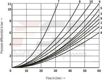
Δp-qV characteristic curves
|
Further characteristic curves: |
|
|
7 |
Symbol “R” in switching position “b” (B → A) |
|
8 |
Symbol “G” and “T” in central position (P → T) |
|
9 |
Symbol “H” in central position (P → T) |
|
Symbols |
Direction of flow |
|||
|
P–A |
P–B |
A–T |
B–T |
|
|
A |
3 |
3 |
– |
– |
|
B |
3 |
3 |
– |
– |
|
C |
1 |
1 |
3 |
1 |
|
D |
5 |
5 |
3 |
3 |
|
E |
3 |
3 |
1 |
1 |
|
F |
1 |
3 |
1 |
1 |
|
G |
6 |
6 |
9 |
9 |
|
H |
2 |
4 |
2 |
2 |
|
J |
1 |
1 |
2 |
1 |
|
L |
3 |
3 |
4 |
9 |
|
M |
2 |
4 |
3 |
3 |
|
P |
3 |
1 |
1 |
1 |
|
Q |
1 |
1 |
2 |
1 |
|
R |
5 |
5 |
4 |
– |
|
T |
10 |
10 |
9 |
9 |
|
U |
3 |
3 |
9 |
4 |
|
V |
1 |
2 |
1 |
1 |
|
W |
1 |
1 |
2 |
2 |
|
Y |
5 |
5 |
3 |
3 |
Minimum pilot pressure dependent on the tank pressure

Notice:
With higher tank pressures, the minimum pilot pressure must be raised according to this diagram.
Performance limits
(measured with HLP46, ϑOil = 40 ±5 °C)
The switching function of the valves is independent from the filtration due to the adhesive effect. To achieve the specified admissible flow values, a full flow filtration with 25 μm is recommended. The flow forces acting within the valves also influence the flow performance.
With 4-directional valves, the specified flow data are therefore valid for normal operation with 2 directions of flow (e. g. from P to A and simultaneous return flow from B to T).
If there is only one direction of flow, the admissible flow may be considerably less in critical cases (e.g. when using a 4-directional valve as 3-directional valve as port A or B is blocked).

Pilot pressure 6 bar > tank pressure
|
Spring return |
Characteristic curve |
Symbols |
|
“no code” |
1 |
A, B |
|
2 |
C, D, Y |
|
|
3 |
E, J, L, U, M, Q, V, W, E1– |
|
|
4 |
F, P |
|
|
5 |
T |
|
|
6 |
G, H |
|
|
7 |
R |
|
|
../O.. |
8 |
A, C, D |
|
../OF.. |
Pilot pressure 10 bar > tank pressure
|
Spring return |
Characteristic curve |
Symbols |
|
“no code” |
1 |
A, B |
|
8 |
C, D, Y, E, G, H, J, L, U, M, Q, V, W, E1– |
|
|
9 |
F, P |
|
|
10 |
R |
|
|
11 |
T |
|
|
../O.. |
8 |
A, C, D |
|
../OF.. |

| 1) |
Example: – Symbol E with spool position "a" → ordering code ..EA.. – Symbol E with spool position “b” → ordering code ..EB.. |
| 2) | Symbol E1-: P → A/B pre-opening |
Notes:
Representation according to DIN ISO 1219-1.Hydraulic interim positions are shown by dashes. Caution in conjunction with differential cylinders due to pressure intensification.
Types of actuation
|
Symbol |
Actuating side |
Control spool return |
Type of actuation |
|
A, C, D |
‒ |
‒ |

|
|
‒ |
../O.. |

|
|
|
‒ |
../OF.. |

|
|
|
B, Y |
‒ |
‒ |

|
|
E, E1, F, G, H, J, L, M, P, Q, R, T, U, V, W |
"a" 1) = .A |
‒ |

|
|
"b" 1) = .B |
‒ |

|
|
|
‒ |
‒ |

|
| 1) | See symbols |
Dimensions in mm

|
|
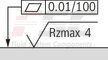
Required surface quality of the valve contact surface |
|
1 |
Valve with 2 spool positions and 2 actuation cylinders |
|
Valve with 3 spool positions and 2 actuation cylinders |
|
|
2 |
Actuation cylinder “a” |
|
3 |
Actuation cylinder “b” |
|
4 |
Cover for valve with 1 actuation cylinder (2 spool positions) |
|
5 |
Same seal rings for ports A, B, P, T |
|
6 |
Name plate |
|
7 |
Porting pattern according to ISO 4401-03-02-0-05 (with or without locating hole) |
Valve mounting screws (separate order)
For reasons of stability, exclusively the following valve mounting screws are to be used:
4 hexagon socket head cap screws
ISO 4762 - M5 x 50 - 10.9-flZn-240h-L
(friction coefficient μtotal = 0.09 … 0.14 according to VDA 235-101)
Material no. R913000064
