

BOSCH REXROTH
R900912693
$567.00 USD
- BOSCH REXROTH
- Material:R900912693
- Model:LFA25H1-7X/F
Due to extremely high demand, please call 920-337-0234 for availability
The Bosch Rexroth LFA25H1-7X/F (R900912693) is a sophisticated way cartridge valve designed for seamless integration into compact block systems. This valve is tailored to accommodate standardized receiving holes according to ISO specifications, ensuring a secure and efficient fit within control blocks. The unique design of the LFA25H1-7X/F allows for the cover to serve as a conduit between the power section and the pilot control valves. This model is versatile in its application, capable of being utilized for pressure, directional, and throttle functions or any combination thereof. Its adaptability makes it an ideal solution for optimizing flow rates across various sections of an actuator, thereby providing cost-effective multi-functionality within hydraulic systems. The LFA25H1-7X/F comprises a control cover that includes essential control bores and may feature additional functionalities such as stroke limitation, hydraulically controlled directional seat valves, or shuttle valves depending on overall function requirements. Furthermore, it accommodates electrically operated directional spool or seat valves if needed. The installation kit that comes with this model consists of several components including a bushing, ring (up to NG), valve poppet (with optional damping nose), and a closing spring. Functionality-wise, this way cartridge valve operates based on pressure differentials across three key areas: A₁, A₂, and A₃. The ratios between these areas are critical in determining the valve's operational characteristics – with A₂ being either 0.7 or 0.3 times the size of A₁ depending on the version. These area ratios influence the opening and closing forces which in turn dictate the spool position within the valve. Additionally, this model features remote control port options and stroke limitation capabilities. It comes from a standard series with varying sizes and component series X designations capable of handling maximum operating pressures up to several hundred bar and accommodating maximum flow rates measured in liters per minute. In summary, the Bosch Rexroth LFA25H1-7X/F way cartridge valve is engineered for precise hydraulic control with customizable features suited for complex system requirements while maintaining efficiency and reliability within its operational parameters.
2-way cartridge valves are elements that have been designed for a compact block design. The power section with connections A and B is installed into the control block in a receiving hole standardized according to ISO 7368 and closed with a cover. In most cases, the cover is also the connection from the control side of the power section to the pilot control valves.
By control with respective pilot control valves, the power section can be applied for pressure, directional and throttle functions or a combination of these functions. Particularly efficient solutions are realized by adjustment of the size to various flows of the individual ways of an actuator. The application of power sections of elements for multiple functions is very cost-effective.
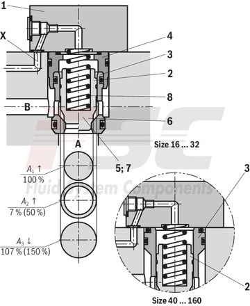
2-way cartridge valves generally consist of control cover (1) and installation kit (2). The control cover contains the control bores and optionally a stroke limitation function, a hydraulically controlled directional seat valve or a shuttle valve according to the required overall function. Additionally, electrically operated directional spool or seat valves can be installed at a control cover. The installation kit consists of a bushing (3), ring (4) (only up to NG32), valve poppet (5), optionally with damping nose (6) or without damping nose (7) as well as closing spring (8).
The function of 2-way cartridge valves is pressure-dependent. This way, three crucial pressurized areas are realized for the function. A1, A2, A3. The area at valve seat A1 is observed as 100 %. Depending on the version, the annulus area A2 realized by grading is 7 % or 50 % of area A1. The area ratio A1 : A2 is respectively either 14.3 : 1 or 2 : 1. The area A3 is identical to the sum of areas A1 + A2. Due to the different area ratios A1 : A2 and the resulting different annulus areas (A2), the area A3 is one time 107 % and another time 150 % of the area A1 at the seat, which is observed as 100 %.
In general, the following applies:
The areas A1 and A2 are effective in opening direction. The area A3 and the spring are effective in closing direction. The direction of action of the resulting force from the opening and closing forces determines the spool position of the 2-way cartridge valve.
The 2-way cartridge valves can be passed from A to B or from B to A. Pressurization of area A3 by pilot oil discharge from channel B or external pilot oil supply, channel A is blocked without leakage.
|
01 |
02 |
03 |
04 |
05 |
06 |
07 |
08 |
09 |
||
|
LFA |
H1 |
– |
7X |
/ |
F |
|
Type |
||
|
01 |
Control cover LFA |
LFA |
|
Size |
||
|
02 |
NG16 |
16 |
|
NG25 |
25 |
|
|
NG32 |
32 |
|
|
NG40 |
40 |
|
|
NG50 |
50 |
|
|
NG63 |
63 |
|
|
Version |
||
|
03 |
Control cover with stroke limitation (hand wheel) and remote control port |
H1 |
|
Component series |
||
|
04 |
Component series 70 ... 79 (70 ... 79: unchanged installation and connection dimensions) |
7X |
|
Remote control port |
||
|
05 |
With remote control port |
F |
|
Nozzle fitting |
||
|
06 |
Orifice in channel X 1) |
X** |
|
Corrosion resistance |
||
|
07 |
None |
no code |
|
Improved corrosion protection (240 h salt spray test according to EN ISO 9227) |
J3 |
|
|
Seal material |
||
|
08 |
NBR seals |
no code |
|
FKM seals |
V |
|
|
Observe compatibility of seals with hydraulic fluid used. (Other seals upon request) |
||
|
Connections, mounting and plug screws |
||
|
09 |
Mounting screws, metric; connections inch thread |
no code |
|
Mounting screws UNC; connections UNF |
/12 |
|
| 1) | This orifice is designed as screw-type orifice. If an orifice is to be installed, the respective code letter with the orifice Ø in 1/10 mm has to be entered in the type designation. Example: A12 = Orifice with Ø1.2 mm in channel A. |
Notice:
Up to NG32, control cover "H" can also be combined with pressure logic inserts type LC..DB..7X. From NG40, special covers type LFA...H.../FDR can be used (see cartridge valve type LC "Information").
Notices:
For ordering code of orifices, see "Accessories" Additional functions with special numbers see "Information".
general
|
Size |
16 | 25 | 32 | 40 | 50 | 63 | ||
|
Weight |
kg |
1.2 | 2.3 | 4 | 7.4 | 10.5 | 21 | |
|
Ambient temperature range |
NBR seals |
°C |
-30 … +60 | |||||
|
FKM seals |
°C |
-20 … +60 | ||||||
|
MTTFD values according to EN ISO 13849 1) |
Years |
150 | ||||||
| 1) | For further details, see data sheet 08012 |
hydraulic
|
Size |
16 | 25 | 32 | 40 | 50 | 63 | ||
|
Maximum operating pressure |
Without directional valve |
bar |
420 | |||||
|
Port X 1) |
bar |
315 350 420 |
||||||
|
Maximum flow 2) |
l/min |
25000 | ||||||
|
Hydraulic fluid |
see table "Hydraulic fluid" | |||||||
|
Hydraulic fluid temperature range |
NBR seals |
°C |
-30 … +80 | |||||
|
FKM seals |
°C |
-20 … +80 | ||||||
|
Viscosity range |
mm²/s |
2.8 … 500 | ||||||
|
Maximum admissible degree of contamination of the hydraulic fluid, cleanliness class according to ISO 4406 (c) 3) |
Class 20/18/15 | |||||||
| 1) | dependent on the attached directional valve |
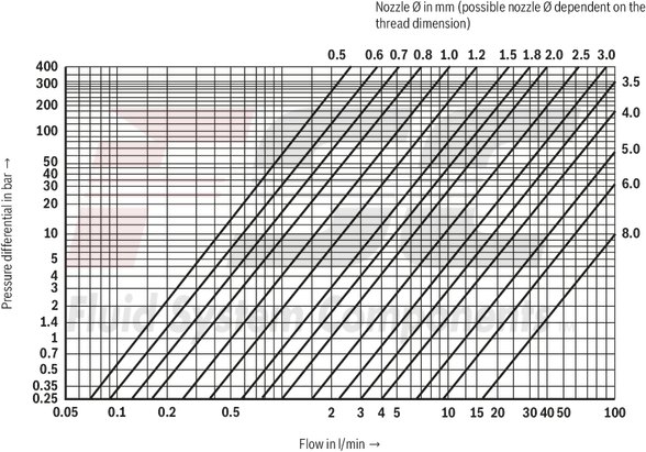
| 2) | NG-dependent; see characteristic curves |
| 3) | The cleanliness classes specified for the components must be adhered to in hydraulic systems. Effective filtration prevents faults and simultaneously increases the life cycle of the components. For the selection of the filters, see www.boschrexroth.com/filter. |
|
Hydraulic fluid |
Classification |
Suitable sealing materials |
Standards |
Data sheet |
|
|
Mineral oils |
HL, HLP, HLPD, HVLP, HVLPD |
NBR, FKM |
DIN 51524 |
90220 |
|
|
Bio-degradable 1) |
Insoluble in water |
HETG |
NBR, FKM |
ISO 15380 |
90221 |
|
HEES |
FKM |
||||
|
Soluble in water |
HEPG |
FKM |
ISO 15380 |
||
|
Flame-resistant |
Water-free |
HFDU (glycol base) |
FKM |
ISO 12922 |
90222 |
|
HFDU (ester base) 1) |
FKM |
||||
|
Containing water 1) |
HFC (Fuchs Hydrotherm 46M, Petrofer Ultra Safe 620) |
NBR |
ISO 12922 |
90223 |
|
|
Important information on hydraulic fluids: For more information and data on the use of other hydraulicfluids, please refer to the data sheets above or contact us. There may be limitations regarding the technical valve data (temperature, pressure range, life cycle, maintenance intervals, etc.). Flame-resistant - containing water: Life cycle as compared to operation with mineral oil HL, HLP 30 … 100%. Maximum hydraulic fluid temperature 60 °C Bio-degradable and flame-resistant: If this hydraulic fluid is used, small amounts of dissolved zinc may get into the hydraulic system. |
|||||
| 1) | Not recommended for corrosion-protected version "J3" (contains zinc) |
For applications outside these parameters, please consult us!
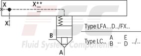
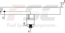
Type LFA . H…/F
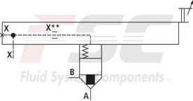
Type LFA . H…/FX**
Size 16 … 40
Dimensions in mm

|
1 |
Name plate at NG16, 25, 32 |
|
2 |
Name plate at NG40 |
|
3 |
Port X optionally as threaded port |
|
NG |
D1 |
D2 |
ØD3 |
H1 |
H2 |
H3 |
H4 max |
▢ L1 |
L2 |
L3 |
T1 |
SW2 |
|
mm |
mm |
mm |
mm |
mm |
mm |
mm |
mm |
mm |
mm |
|||
| 16 | G 1/8 | M6 | 52 | 35 | 12 | 15 | 90 | 65 | 32.5 | 4 | 8 | 21 |
| 25 | G1/4 | M6 | 80 | 40 | 16 | 24 | 95 | 85 | 42.5 | 5 | 12 | 22 |
| 32 | G1/4 | M6 | 80 | 75 | 16 | 28 | 120 | 100 | 50 | 5 | 12 | 27 |
| 40 | G1/2 | M8 x 1 | 100 | 95 | 30 | 32 | 160 | 25 | 72 | 5 | 14 | 46 |
|
1 |
Name plate |
|
2 |
Port X optionally as threaded port |
|
NG |
D1 |
D2 |
H1 |
H2 |
H3 |
H6 max |
▢ L1 |
L2 |
L3 |
T1 |
SW2 |
SW5 |
|
mm |
mm |
mm |
mm |
mm |
mm |
mm |
mm |
mm |
mm |
|||
| 50 | G1/2 | M8 x 1 | 110 | 32 | 34 | 230 | 140 | 80 | 5 | 14 | 55 | 46 |
| 63 | G3/4 | G3/8 | 125 | 40 | 50 | 250 | 180 | 90 | 5 | 16 | 65 | 55 |
Mounting screws (included in scope of delivery)
|
Hexagon socket head cap screws ISO 4762 - 10.9-flZn/nc/480h/C 1) |
||
|
Size |
Quantity |
Tightening torque MA in Nm ±10 % |
|
16 |
4 |
30 |
|
25 |
4 |
100 |
|
32 |
4 |
240 |
|
40 |
4 |
480 |
|
50 |
4 |
480 |
|
63 |
4 |
1600 |
|
80 |
8 |
800 |
|
100 |
8 |
1600 |
|
125 |
8 |
3100 |
|
160 |
12 |
5000 |
| 1) | Hexagon socket head cap screws UNC, see data sheet 08936 |
Notices:
The specified tightening torques stated are guidelines when using screws with the specified friction coefficients and when using a manual torque wrench (tolerance ± 10%). The specified tightening torques were calculated with total friction coefficient μtotal = 0.09 ... 0.14; adjust in case of modified surfaces. Supplied mounting screws are only suitable for direct assembly on a block. If an intermediate cover is used, mounting screws have to be designed accordingly longer.Connection dimensions according to ISO 7368
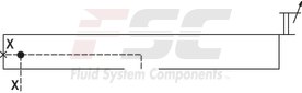
Size 16 ... 63
Dimensions in mm
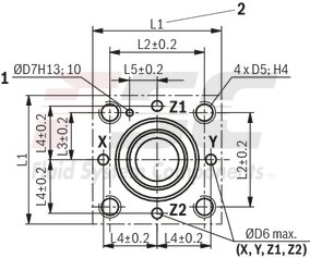
|
1 |
Bore for locating pin |
|
2 |
80 mm only at control cover for directional valve set-up NG16 (axis X–Y bore) |
|
NG |
16 | 25 | 32 | 40 | 50 | 63 | |
|
ØD5 1) |
M8 | M12 | M16 | M20 | M20 | M30 | |
|
ØD6 |
mm |
4 | 6 | 8 | 10 | 10 | 12 |
|
ØD7H13 |
mm |
4 | 6 | 6 | 6 | 8 | 8 |
|
H4 |
mm |
20 | 25 | 35 | 45 | 45 | 65 |
|
L1 |
mm |
65 80 |
85 - |
102 - |
125 - |
140 - |
180 - |
|
L2 |
mm |
46 - |
58 - |
70 - |
85 - |
100 - |
125 - |
|
L3 |
mm |
23 | 29 | 35 | 42.5 | 50 | 62.5 |
|
L4 |
mm |
25 | 33 | 41 | 50 | 58 | 75 |
|
L5 |
mm |
10.5 | 16 | 17 | 23 | 30 | 38 |
| 1) | Mounting thread for version "/12" see data sheet 08936 |
Notice:
The dimensions are nominal dimensions which are subject to tolerances.
Orifice symbol
|
Orifice symbol |
Ordering code |
|||
|
A** |

|
A** |
This orifice is designed as screw-type orifice. If an orifice is to be installed, the respective code letter with the orifice Ø in 1/10 mm has to be entered in the type designation. Example: A12 = Orifice with Ø1.2 mm in channel A. |
|
|
Ø1,2 |

|
This orifice is designed as bore. No specifications are made in the type designation. (Orifice Ø in mm) |
||
|
Z12 |

|
This orifice is designed as screw-type orifice. This is a standard orifice. No specifications are made in the type designation. (Orifice Ø in 1/10 mm) |
||
Additional functions with special numbers (upon request)
|
Symbol |
Type |
Size |
Description / special characteristic |
|
LFA…H…/FDR… |
40 … 80 |
Stroke limitation cover for pressure logics |
Orifice selection
Orifice selection
Orifices
|
Orifice Ø in mm |
Order numbers |
Material numbers |
||||||
|
M6 conical |
M8 x 1 conical |
G 1/8 conical |
G 1/4 conical |
G 3/8 conical |
G 1/2 conical |
G 1 conical |
||
|
– |
00 |
– |
– |
– |
– |
– |
– |
– |
|
0,5 |
05 |
R913040356 |
R913017600 |
R913030187 |
R913040456 |
– |
– |
– |
|
0,6 |
06 |
R913040358 |
R913017605 |
R913017606 |
R913020197 |
– |
– |
– |
|
0,7 |
07 |
R913040360 |
R913017609 |
R913046092 |
– |
– |
– |
– |
|
0,8 |
08 |
R913029447 |
R913017614 |
R913017616 |
R913017615 |
R913040481 |
R913040499 |
– |
|
1,0 |
10 |
R913019186 |
R913017621 |
R913024679 |
R913017622 |
R913040484 |
R913040500 |
– |
|
1,2 |
12 |
R913040362 |
R913017627 |
R913017629 |
R913017628 |
R913040486 |
R913040501 |
– |
|
1,5 |
15 |
R913028337 |
R913017637 |
R913017639 |
R913017638 |
R913040488 |
R913028317 |
– |
|
1,8 |
18 |
R913030186 |
R913017644 |
R913017646 |
R913017645 |
R913040489 |
R913045913 |
– |
|
2,0 |
20 |
R913029870 |
R913017651 |
R913040450 |
R913017652 |
R913028417 |
R913028336 |
– |
|
2,5 |
25 |
R913032543 |
R913035796 |
R913017656 |
R913019582 |
R913040493 |
R913040502 |
– |
|
3,0 |
30 |
R913040368 |
R913017661 |
R913017663 |
R913017662 |
R913018266 |
R913040503 |
R913040467 |
|
3,5 |
35 |
– |
R913017667 |
R913040452 |
R913040463 |
R913028318 |
R913019856 |
R913040469 |
|
4,0 |
40 |
– |
R913017670 |
R913027078 |
R913040464 |
R913018265 |
R913029168 |
R913040470 |
|
4,5 |
45 |
– |
R913046571 |
R913017671 |
R913040465 |
– |
R913040506 |
– |
|
5,0 |
50 |
– |
– |
R913017673 |
R913040468 |
R913023871 |
R913019857 |
R913040471 |
|
5,5 |
55 |
– |
– |
R913027077 |
– |
R913040495 |
R913053659 |
– |
|
6,0 |
60 |
– |
– |
– |
– |
R913023870 |
R913028418 |
R913020247 |
|
7,0 |
70 |
– |
– |
– |
R913040461 |
R913017675 |
R913040509 |
– |
|
7,5 |
75 |
– |
– |
– |
– |
R913023430 |
– |
R913018328 |
|
8,0 |
80 |
– |
– |
– |
– |
R913046570 |
R913040510 |
R913020246 |
|
closed |
99 |
R913019128 |
R913019129 |
R913019137 |
R913019136 |
R913019138 |
– |
R913019140 |
Plug screws
|
Thread |
Tightening torque MA in Nm ±10 % |
|
G 1/8 |
12 |
|
G 1/4 |
30 |
|
G 3/8 |
55 |
|
G 1/2 |
80 |
|
G 3/4 |
135 |
|
G 1 |
225 |
|
G 1 1/4 |
360 |