

BOSCH REXROTH
R901155244
$815.00 USD
- BOSCH REXROTH
- Material:R901155244
- Model:3SEC 6 E35-1X/CG24N9K4
Due to extremely high demand, please call 920-337-0234 for availability
The Bosch Rexroth 3SEC 6 E35-1X/CG24N9K4 (R901155244) is a highly reliable and efficient directional seat valve designed for controlling the start, stop, and direction of fluid flow within hydraulic systems. This direct-operated valve is equipped with solenoid actuation and features a robust housing that contains up to four valve systems, which can be switched in different configurations based on the application needs. The solenoid operates the control spool via an actuation element and ball, with a spring ensuring the spool returns to its starting position. The valve includes a manual override function that allows it to be operated without solenoid power, providing an additional layer of operational flexibility. Users must ensure that the maximum flow is not exceeded; if necessary, an orifice insert can be utilized to limit flow according to specific functional requirements. The model also offers a throttle insert for controlling consumption speed—useful in applications such as workpiece clamping—while check valve inserts in P and T ports enable free flow in one direction and block it in the opposite. This Bosch Rexroth valve boasts a porting pattern according to ISO standards and ensures leak-free closure of blocked ports. It is capable of reliable switching even under pressure for extended periods of standstill. The wet-pin DC solenoids come with detachable coils for easy maintenance, and AC voltage compatibility is possible through a rectifier. Additionally, the solenoid coil can be rotated by 90 degrees for flexible installation options. Electrical connections are versatile, offering both individual connection options and central connection via double mating connector. For added convenience, there's an option for concealed manual override. This valve conforms to DIN EN ISO standards and falls under category 6E35-1X for component series X. It can handle maximum operating pressures up to bar and accommodate maximum flow rates of l/min as specified by operational conditions.
General
The SEC type directional valve is a directional seat valve with solenoid actuation. It controls the start, stop and direction of flow and mainly consists of a housing (1), the solenoid (2) as well as the hardened valve system (3).
The manual override allows the switching of the valve without solenoid energization.
Basic principle
In the starting position, the control spool (5) is pressed onto the seat by means of the spring (4). The force of the solenoid (2) takes effect on the control spool (5) via an actuation element (6) and the ball (7). Depending on the spool, up to four valve systems (3) are installed in the housing, which can be switched differently.
Attention!
It is to be ensured that the maximum flow indicated is not exceeded! If applicable, an orifice insert is to be used for flow limitation (see functional description).
Depending on the production tolerances, a pump or tank pre-opening of the valve occurs. For this reason, for valves of the same type, different pressure gradients can occur during the switching process.
One valve alone may not be used for holding loads or positions.

Orifice insert
The orifice insert must be used if, based on the given operating conditions, flows which exceed the performance limit of the valve can occur during the switching processes.
Examples:
Accumulator operation, use as pilot control valve with internal pilot fluid tapping.
Throttle insert
The throttle insert is used for the control of the consumption speed (e.g. time for workpiece clamping). Depending on the case of application, a supply or sequence control is possible.

Check valve insert
The check valve insert in P enables a free flow from P to A/B and closes the flow from A/B to P.
The check valve insert in T enables a free flow from A/B to T and closes the flow from T to A/B.

|
01 |
02 |
03 |
04 |
05 |
|
06 |
07 |
08 |
09 |
|
10 |
11 |
12 |
13 |
|
|
SEC |
6 |
|
1X |
/ |
C |
|
|
|
/ |
|
|
|
* |
|
Main ports |
|||||
|
01 |
2 |
2 |
|||
|
3 |
3 |
||||
|
4 |
4 |
||||
|
02 |
Seat valve |
SEC |
|||
|
03 |
Size 6 |
6 |
|||
|
04 |
Symbol e.g. E; for the possible design, see symbols |
||||
|
05 |
Component series 10 ... 19 (10 ... 19: unchanged installation and connection dimensions) |
1X |
|||
|
06 |
Solenoid with detachable coil |
C |
|||
|
07 |
Direct voltage 12 V |
G12 |
|||
|
Direct voltage 24 V |
G24 |
||||
|
Direct voltage 26 V |
G26 |
||||
|
Direct voltage 48 V |
G48 |
||||
|
Nominal voltage 96 V at DC solenoid with operation with AC voltage mains (AC voltage mains 110 V - 50/60 Hz with an admissible voltage tolerance of +/- 10 %) |
G96 |
||||
|
Nominal voltage 110 V at DC solenoid with operation with AC voltage mains (AC voltage mains 120 V – 60 Hz with an admissible voltage tolerance of +/-10 %) |
G110 |
||||
|
Direct voltage 125 V |
G125 |
||||
|
Nominal voltage 205 V at DC solenoid with operation with AC voltage mains (AC voltage mains 230 V - 50/60 Hz with an admissible voltage tolerance of +/-10 %) |
G205 |
||||
|
Direct voltage 220 V |
G220 |
||||
|
08 |
Without manual override |
no code |
|||
|
With manual override |
N |
||||
|
With concealed manual override |
N9 |
||||
|
Electrical connection |
|||||
|
09 |
without mating connector, individual connection with connector according to DIN EN 175301-803 |
K42; 3; 4) |
|||
|
without mating connector, individual connection, 4-pole, with connector M12 x 1, integrated interference protection circuit, status LED |
K72L2) |
||||
|
without mating connector, individual connection, 4-pole, with connector M12 x 1 (no connection between pin 1 and pin 2), integrated interference protection circuit, status LED |
K73L2) |
||||
|
without mating connector, with connector AMP Junior-Timer |
C4 2) |
||||
|
Coil connection combination |
|||||
|
|
K4 |
K72L |
K73L |
C4 |
|
|
G12 |
✔ |
– |
– |
✔ |
|
|
G24 |
✔ |
✔ |
✔ |
✔ |
|
|
G26 |
✔ |
– |
– |
✔ |
|
|
G48 |
✔ |
– |
– |
– |
|
|
G96 |
✔ |
– |
– |
– |
|
|
G110 |
✔ |
– |
– |
– |
|
|
G125 |
✔ |
– |
– |
– |
|
|
G205 |
✔ |
– |
– |
– |
|
|
G220 |
✔ |
– |
– |
– |
|
|
10 |
without check valve insert, without throttle insert, without orifice insert |
no code |
|||
|
with check valve insert, with throttle insert, with orifice insert (for further information, please refer to the functional description and selection table) |
P... |
||||
|
Seal material |
|||||
|
11 |
NBR seals |
no code |
|||
|
FKM seals (other seals upon request) |
V |
||||
|
Observe compatibility of seals with hydraulic fluid used. |
|||||
|
12 |
With locating hole 1) |
no code |
|||
|
With locating hole and locking pin ISO 8752-3x8-St |
/62 |
||||
|
13 |
Further details in the plain text |
* |
|||
| 1) Locking pin ISO 8752-3x8-St, material no. R900005694 (separate order) | |
| 2) Mating connectors, separate order, see data sheet 08006. | |
| 3) For connection to the AC voltage mains , a DC solenoid controlled via a rectifier is to be used (see table). | |
| In the event of an individual connection, a mating connector with integrated rectifier can be used (separate order, see data sheet 08006). | |
| 4) Double valve mating connectors for central connection, separate order, see data sheet 08006. |
Preferred types and standard units are contained in the EPS (standard price list).
Selection table: Orifice insert, throttle insert and check valve insert
Order example:
Orifice insert Ø0.6 mm in channel P Orifice insert Ø0.6 mm in channel A Check valve insert in channel T→ ordering code „P069“
|
Ordering code |
Orifice insert in channel P |
|
P001 |
0,6 |
|
P002 |
0,7 |
|
P003 |
0,8 |
|
P004 |
1,0 |
|
P005 |
1,2 |
|
P006 |
1,5 |
|
P007 |
1,8 |
|
P008 |
2,0 |
|
P009 |
2,2 |
|
P010 |
3,0 |
|
P011 |
3,5 |
|
Ordering code |
Check valve in channel P |
Check valve in channel T |
|
P012 |
✔ |
– |
|
P013 |
✔ |
✔ |
|
Ordering code |
Orifice insert in channel P |
Check valve in channel T |
|
P014 |
0,6 |
✔ |
|
P015 |
0,7 |
✔ |
|
P016 |
0,8 |
✔ |
|
P017 |
1,0 |
✔ |
|
P018 |
1,2 |
✔ |
|
P019 |
1,5 |
✔ |
|
P020 |
1,8 |
✔ |
|
P021 |
2,0 |
✔ |
|
P022 |
2,2 |
✔ |
|
P023 |
3,0 |
✔ |
|
P024 |
3,5 |
✔ |
|
Ordering code |
Orifice insert in channel A |
|
P025 |
0,6 |
|
P026 |
0,7 |
|
P027 |
0,8 |
|
P028 |
1,0 |
|
P029 |
1,2 |
|
P030 |
1,5 |
|
P031 |
1,8 |
|
P032 |
2,0 |
|
P033 |
2,2 |
|
P034 |
3,0 |
|
P035 |
3,5 |
|
Ordering code |
Orifice insert in channel B |
|
P036 |
0,6 |
|
P037 |
0,7 |
|
P038 |
0,8 |
|
P039 |
1,0 |
|
P040 |
1,2 |
|
P041 |
1,5 |
|
P042 |
1,8 |
|
P043 |
2,0 |
|
P044 |
2,2 |
|
P045 |
3,0 |
|
P046 |
3,5 |
|
Ordering code |
Orifice insert in channel A |
Orifice insert in channel B |
|
P047 |
0,6 |
0,6 |
|
P048 |
0,7 |
0,7 |
|
P049 |
0,8 |
0,8 |
|
P050 |
1,0 |
1,0 |
|
P051 |
1,2 |
1,2 |
|
P052 |
1,5 |
1,5 |
|
P053 |
1,8 |
1,8 |
|
P054 |
2,0 |
2,0 |
|
P055 |
2,2 |
2,2 |
|
P056 |
3,0 |
3,0 |
|
P057 |
3,5 |
3,5 |
|
Ordering code |
Orifice insert in channel P |
Orifice insert in channel A |
|
P058 |
0,6 |
0,6 |
|
P059 |
0,7 |
0,7 |
|
P060 |
0,8 |
0,8 |
|
P061 |
1,0 |
1,0 |
|
P062 |
1,2 |
1,2 |
|
P063 |
1,5 |
1,5 |
|
P064 |
1,8 |
1,8 |
|
P065 |
2,0 |
2,0 |
|
P066 |
2,2 |
2,2 |
|
P067 |
3,0 |
3,0 |
|
P068 |
3,5 |
3,5 |
|
Ordering code |
Orifice insert in channel P |
Orifice insert in channel A |
Check valve in channel T |
|
P069 |
0,6 |
0,6 |
✔ |
|
P070 |
0,7 |
0,7 |
✔ |
|
P071 |
0,8 |
0,8 |
✔ |
|
P072 |
1,0 |
1,0 |
✔ |
|
P073 |
1,2 |
1,2 |
✔ |
|
P074 |
1,5 |
1,5 |
✔ |
|
P075 |
1,8 |
1,8 |
✔ |
|
P076 |
2,0 |
2,0 |
✔ |
|
P077 |
2,2 |
2,2 |
✔ |
|
P078 |
3,0 |
3,0 |
✔ |
|
P079 |
3,5 |
3,5 |
✔ |
|
Ordering code |
Orifice insert in channel P |
Orifice insert in channel B |
|
P080 |
0,6 |
0,6 |
|
P081 |
0,7 |
0,7 |
|
P082 |
0,8 |
0,8 |
|
P083 |
1,0 |
1,0 |
|
P084 |
1,2 |
1,2 |
|
P085 |
1,5 |
1,5 |
|
P086 |
1,8 |
1,8 |
|
P087 |
2,0 |
2,0 |
|
P088 |
2,2 |
2,2 |
|
P089 |
3,0 |
3,0 |
|
P090 |
3,5 |
3,5 |
|
Ordering code |
Orifice insert in channel P |
Orifice insert in channel B |
Check valve in channel T |
|
P091 |
0,6 |
0,6 |
✔ |
|
P092 |
0,7 |
0,7 |
✔ |
|
P093 |
0,8 |
0,8 |
✔ |
|
P094 |
1,0 |
1,0 |
✔ |
|
P095 |
1,2 |
1,2 |
✔ |
|
P096 |
1,5 |
1,5 |
✔ |
|
P097 |
1,8 |
1,8 |
✔ |
|
P098 |
2,0 |
2,0 |
✔ |
|
P099 |
2,2 |
2,2 |
✔ |
|
P100 |
3,0 |
3,0 |
✔ |
|
P101 |
3,5 |
3,5 |
✔ |
|
Ordering code |
Throttle insert (discharge) in channel A |
Throttle insert (discharge) in channel B |
Throttle insert (supply) in channel A |
Throttle insert (supply) in channel B |
|
P102 |
0,7 |
– |
– |
– |
|
P103 |
– |
0,7 |
– |
– |
|
P104 |
– |
– |
0,7 |
– |
|
P105 |
– |
– |
– |
0,7 |
|
P106 |
0,7 |
0,7 |
– |
– |
|
P107 |
– |
– |
0,7 |
0,7 |
|
Ordering code |
Throttle insert (discharge) in channel A |
Throttle insert (discharge) in channel B |
Throttle insert (supply) in channel A |
Throttle insert (supply) in channel B |
Check valve in channel P |
|
P108 |
0,7 |
– |
– |
– |
✔ |
|
P109 |
– |
0,7 |
– |
– |
✔ |
|
P110 |
– |
– |
0,7 |
– |
✔ |
|
P111 |
– |
– |
– |
0,7 |
✔ |
|
P112 |
0,7 |
0,7 |
– |
– |
✔ |
|
P113 |
– |
– |
0,7 |
0,7 |
✔ |
|
Ordering code |
Throttle insert (discharge) in channel A |
Throttle insert (discharge) in channel B |
Throttle insert (supply) in channel A |
Throttle insert (supply) in channel B |
Check valve in channel P |
Check valve in channel T |
|
P114 |
0,7 |
– |
– |
– |
✔ |
✔ |
|
P115 |
– |
0,7 |
– |
– |
✔ |
✔ |
|
P116 |
– |
– |
0,7 |
– |
✔ |
✔ |
|
P117 |
– |
– |
– |
0,7 |
✔ |
✔ |
|
P118 |
0,7 |
0,7 |
– |
– |
✔ |
✔ |
|
Ordering code |
Throttle insert (discharge) in channel A |
Throttle insert (discharge) in channel B |
Throttle insert (supply) in channel A |
Throttle insert (supply) in channel B |
|
P120 |
1,0 |
– |
– |
– |
|
P121 |
– |
1,0 |
– |
– |
|
P122 |
– |
– |
1,0 |
– |
|
P123 |
– |
– |
– |
1,0 |
|
P124 |
1,0 |
1,0 |
– |
– |
|
P125 |
– |
– |
1,0 |
1,0 |
|
Ordering code |
Throttle insert (discharge) in channel A |
Throttle insert (discharge) in channel B |
Throttle insert (supply) in channel A |
Throttle insert (supply) in channel B |
Check valve in channel P |
|
P126 |
1,0 |
– |
– |
– |
✔ |
|
P127 |
– |
1,0 |
– |
– |
✔ |
|
P128 |
– |
– |
1,0 |
– |
✔ |
|
P129 |
– |
– |
– |
1,0 |
✔ |
|
P130 |
1,0 |
1,0 |
– |
– |
✔ |
|
P131 |
– |
– |
1,0 |
1,0 |
✔ |
|
Ordering code |
Throttle insert (discharge) in channel A |
Throttle insert (discharge) in channel B |
Throttle insert (supply) in channel A |
Throttle insert (supply) in channel B |
Check valve in channel P |
Check valve in channel T |
|
P132 |
1,0 |
– |
– |
– |
✔ |
✔ |
|
P133 |
– |
1,0 |
– |
– |
✔ |
✔ |
|
P134 |
– |
– |
1,0 |
– |
✔ |
✔ |
|
P135 |
– |
– |
– |
1,0 |
✔ |
✔ |
|
P136 |
1,0 |
1,0 |
– |
– |
✔ |
✔ |
|
P137 |
– |
– |
1,0 |
1,0 |
✔ |
✔ |
|
Ordering code |
Throttle insert (discharge) in channel A |
Throttle insert (discharge) in channel B |
Throttle insert (supply) in channel A |
Throttle insert (supply) in channel B |
|
P138 |
1,2 |
– |
– |
– |
|
P139 |
– |
1,2 |
– |
– |
|
P140 |
– |
– |
1,2 |
– |
|
P141 |
– |
– |
– |
1,2 |
|
P142 |
1,2 |
1,2 |
– |
– |
|
P143 |
– |
– |
1,2 |
1,2 |
|
Ordering code |
Throttle insert (discharge) in channel A |
Throttle insert (discharge) in channel B |
Throttle insert (supply) in channel A |
Throttle insert (supply) in channel B |
Check valve in channel P |
|
P144 |
1,2 |
– |
– |
– |
✔ |
|
P145 |
– |
1,2 |
– |
– |
✔ |
|
P146 |
– |
– |
1,2 |
– |
✔ |
|
P147 |
– |
– |
– |
1,2 |
✔ |
|
P148 |
1,2 |
1,2 |
– |
– |
✔ |
|
P149 |
– |
– |
1,2 |
1,2 |
✔ |
|
Ordering code |
Throttle insert (discharge) in channel A |
Throttle insert (discharge) in channel B |
Throttle insert (supply) in channel A |
Throttle insert (supply) in channel B |
Check valve in channel P |
Check valve in channel T |
|
P150 |
1,2 |
– |
– |
– |
✔ |
✔ |
|
P151 |
– |
1,2 |
– |
– |
✔ |
✔ |
|
P152 |
– |
– |
1,2 |
– |
✔ |
✔ |
|
P153 |
– |
– |
– |
1,2 |
✔ |
✔ |
|
P154 |
1,2 |
1,2 |
– |
– |
✔ |
✔ |
|
P155 |
– |
– |
1,2 |
1,2 |
✔ |
✔ |
|
Ordering code |
Throttle insert (discharge) in channel A |
Throttle insert (discharge) in channel B |
Throttle insert (supply) in channel A |
Throttle insert (supply) in channel B |
|
P156 |
1,5 |
– |
– |
– |
|
P157 |
– |
1,5 |
– |
– |
|
P158 |
– |
– |
1,5 |
– |
|
P159 |
– |
– |
– |
1,5 |
|
P160 |
1,5 |
1,5 |
– |
– |
|
P161 |
– |
– |
1,5 |
1,5 |
|
Ordering code |
Throttle insert (discharge) in channel A |
Throttle insert (discharge) in channel B |
Throttle insert (supply) in channel A |
Throttle insert (supply) in channel B |
Check valve in channel P |
|
P162 |
1,5 |
– |
– |
– |
✔ |
|
P163 |
– |
1,5 |
– |
– |
✔ |
|
P164 |
– |
– |
1,5 |
– |
✔ |
|
P165 |
– |
– |
– |
1,5 |
✔ |
|
P166 |
1,5 |
1,5 |
– |
– |
✔ |
|
P167 |
– |
– |
1,5 |
1,5 |
✔ |
|
Ordering code |
Throttle insert (discharge) in channel A |
Throttle insert (discharge) in channel B |
Throttle insert (supply) in channel A |
Throttle insert (supply) in channel B |
Check valve in channel P |
Check valve in channel T |
|
P168 |
1,5 |
– |
– |
– |
✔ |
✔ |
|
P169 |
– |
1,5 |
– |
– |
✔ |
✔ |
|
P170 |
– |
– |
1,5 |
– |
✔ |
✔ |
|
P171 |
– |
– |
– |
1,5 |
✔ |
✔ |
|
P172 |
1,5 |
1,5 |
– |
– |
✔ |
✔ |
|
P173 |
– |
– |
1,5 |
1,5 |
✔ |
✔ |
|
Ordering code |
Throttle insert (discharge) in channel A |
Throttle insert (discharge) in channel B |
Throttle insert (supply) in channel A |
Throttle insert (supply) in channel B |
|
P174 |
2,0 |
– |
– |
– |
|
P175 |
– |
2,0 |
– |
– |
|
P176 |
– |
– |
2,0 |
– |
|
P177 |
– |
– |
– |
2,0 |
|
P178 |
2,0 |
2,0 |
– |
– |
|
P179 |
– |
– |
2,0 |
2,0 |
|
Ordering code |
Throttle insert (discharge) in channel A |
Throttle insert (discharge) in channel B |
Throttle insert (supply) in channel A |
Throttle insert (supply) in channel B |
Check valve in channel P |
|
P180 |
2,0 |
– |
– |
– |
✔ |
|
P181 |
– |
2,0 |
– |
– |
✔ |
|
P182 |
– |
– |
2,0 |
– |
✔ |
|
P183 |
– |
– |
– |
2,0 |
✔ |
|
P184 |
2,0 |
2,0 |
– |
– |
✔ |
|
P185 |
– |
– |
2,0 |
2,0 |
✔ |
|
Ordering code |
Throttle insert (discharge) in channel A |
Throttle insert (discharge) in channel B |
Throttle insert (supply) in channel A |
Throttle insert (supply) in channel B |
Check valve in channel P |
Check valve in channel T |
|
P186 |
2,0 |
– |
– |
– |
✔ |
✔ |
|
P187 |
– |
2,0 |
– |
– |
✔ |
✔ |
|
P188 |
– |
– |
2,0 |
– |
✔ |
✔ |
|
P189 |
– |
– |
– |
2,0 |
✔ |
✔ |
|
P190 |
2,0 |
2,0 |
– |
– |
✔ |
✔ |
|
P191 |
– |
– |
2,0 |
2,0 |
✔ |
✔ |
|
Ordering code |
Throttle insert (discharge) in channel A |
Throttle insert (discharge) in channel B |
Throttle insert (supply) in channel A |
Throttle insert (supply) in channel B |
|
P192 |
2,5 |
– |
– |
– |
|
P193 |
– |
2,5 |
– |
– |
|
P194 |
– |
– |
2,5 |
– |
|
P195 |
– |
– |
– |
2,5 |
|
P196 |
2,5 |
2,5 |
– |
– |
|
P197 |
– |
– |
2,5 |
2,5 |
|
Ordering code |
Throttle insert (discharge) in channel A |
Throttle insert (discharge) in channel B |
Throttle insert (supply) in channel A |
Throttle insert (supply) in channel B |
Check valve in channel P |
|
P198 |
2,5 |
– |
– |
– |
✔ |
|
P199 |
– |
2,5 |
– |
– |
✔ |
|
P200 |
– |
– |
2,5 |
– |
✔ |
|
P201 |
– |
– |
– |
2,5 |
✔ |
|
P202 |
2,5 |
2,5 |
– |
– |
✔ |
|
P203 |
– |
– |
2,5 |
2,5 |
✔ |
|
Ordering code |
Throttle insert (discharge) in channel A |
Throttle insert (discharge) in channel B |
Throttle insert (supply) in channel A |
Throttle insert (supply) in channel B |
Check valve in channel P |
Check valve in channel T |
|
P204 |
2,5 |
– |
– |
– |
✔ |
✔ |
|
P205 |
– |
2,5 |
– |
– |
✔ |
✔ |
|
P206 |
– |
– |
2,5 |
– |
✔ |
✔ |
|
P207 |
– |
– |
– |
2,5 |
✔ |
✔ |
|
P208 |
2,5 |
2,5 |
– |
– |
✔ |
✔ |
|
P209 |
– |
– |
2,5 |
2,5 |
✔ |
✔ |
|
Ordering code |
Throttle insert (discharge) in channel A |
Throttle insert (discharge) in channel B |
|
P210 |
0,7 |
1,0 |
|
P211 |
0,7 |
1,2 |
|
P212 |
0,7 |
1,5 |
|
P213 |
0,7 |
2,0 |
|
P214 |
0,7 |
2,5 |
|
Ordering code |
Throttle insert (discharge) in channel A |
Throttle insert (discharge) in channel B |
Check valve in channel P |
|
P215 |
0,7 |
1,0 |
✔ |
|
P216 |
0,7 |
1,2 |
✔ |
|
P217 |
0,7 |
1,5 |
✔ |
|
P218 |
0,7 |
2,0 |
✔ |
|
P219 |
0,7 |
2,5 |
✔ |
|
Ordering code |
Throttle insert (discharge) in channel A |
Throttle insert (discharge) in channel B |
Check valve in channel P |
Check valve in channel T |
|
P220 |
0,7 |
1,0 |
✔ |
✔ |
|
P221 |
0,7 |
1,2 |
✔ |
✔ |
|
P222 |
0,7 |
1,5 |
✔ |
✔ |
|
P223 |
0,7 |
2,0 |
✔ |
✔ |
|
P224 |
0,7 |
2,5 |
✔ |
✔ |
|
Ordering code |
Throttle insert (supply) in channel A |
Throttle insert (supply) in channel B |
|
P225 |
0,7 |
1,0 |
|
P226 |
0,7 |
1,2 |
|
P227 |
0,7 |
1,5 |
|
P228 |
0,7 |
2,0 |
|
P229 |
0,7 |
2,5 |
|
Ordering code |
Throttle insert (supply) in channel A |
Throttle insert (supply) in channel B |
Check valve in channel P |
|
P230 |
0,7 |
1,0 |
✔ |
|
P231 |
0,7 |
1,2 |
✔ |
|
P232 |
0,7 |
1,5 |
✔ |
|
P233 |
0,7 |
2,0 |
✔ |
|
P234 |
0,7 |
2,5 |
✔ |
|
Ordering code |
Throttle insert (supply) in channel A |
Throttle insert (supply) in channel B |
Check valve in channel P |
Check valve in channel T |
|
P235 |
0,7 |
1,0 |
✔ |
✔ |
|
P236 |
0,7 |
1,2 |
✔ |
✔ |
|
P237 |
0,7 |
1,5 |
✔ |
✔ |
|
P238 |
0,7 |
2,0 |
✔ |
✔ |
|
P239 |
0,7 |
2,5 |
✔ |
✔ |
|
Ordering code |
Throttle insert (discharge) in channel A |
Throttle insert (discharge) in channel B |
|
P240 |
1,0 |
1,2 |
|
P241 |
1,0 |
1,5 |
|
P242 |
1,0 |
2,0 |
|
P243 |
1,0 |
2,5 |
|
Ordering code |
Throttle insert (discharge) in channel A |
Throttle insert (discharge) in channel B |
Check valve in channel P |
|
P244 |
1,0 |
1,2 |
✔ |
|
P245 |
1,0 |
1,5 |
✔ |
|
P246 |
1,0 |
2,0 |
✔ |
|
P247 |
1,0 |
2,5 |
✔ |
|
Ordering code |
Throttle insert (discharge) in channel A |
Throttle insert (discharge) in channel B |
Check valve in channel P |
Check valve in channel T |
|
P248 |
1,0 |
1,2 |
✔ |
✔ |
|
P249 |
1,0 |
1,5 |
✔ |
✔ |
|
P250 |
1,0 |
2,0 |
✔ |
✔ |
|
P251 |
1,0 |
2,5 |
✔ |
✔ |
|
Ordering code |
Throttle insert (supply) in channel A |
Throttle insert (supply) in channel B |
|
P252 |
1,0 |
1,2 |
|
P253 |
1,0 |
1,5 |
|
P254 |
1,0 |
2,0 |
|
P255 |
1,0 |
2,5 |
|
Ordering code |
Throttle insert (supply) in channel A |
Throttle insert (supply) in channel B |
Check valve in channel P |
|
P256 |
1,0 |
1,2 |
✔ |
|
P257 |
1,0 |
1,5 |
✔ |
|
P258 |
1,0 |
2,0 |
✔ |
|
P259 |
1,0 |
2,5 |
✔ |
|
Ordering code |
Throttle insert (supply) in channel A |
Throttle insert (supply) in channel B |
Check valve in channel P |
Check valve in channel T |
|
P260 |
1,0 |
1,2 |
✔ |
✔ |
|
P261 |
1,0 |
1,5 |
✔ |
✔ |
|
P262 |
1,0 |
2,0 |
✔ |
✔ |
|
P263 |
1,0 |
2,5 |
✔ |
✔ |
|
Ordering code |
Throttle insert (discharge) in channel A |
Throttle insert (discharge) in channel B |
|
P264 |
1,2 |
1,0 |
|
P265 |
1,2 |
1,5 |
|
P266 |
1,2 |
2,0 |
|
P267 |
1,2 |
2,5 |
|
Ordering code |
Throttle insert (discharge) in channel A |
Throttle insert (discharge) in channel B |
Check valve in channel P |
|
P268 |
1,2 |
1,0 |
✔ |
|
P269 |
1,2 |
1,5 |
✔ |
|
P270 |
1,2 |
2,0 |
✔ |
|
P271 |
1,2 |
2,5 |
✔ |
|
Ordering code |
Throttle insert (discharge) in channel A |
Throttle insert (discharge) in channel B |
Check valve in channel P |
Check valve in channel T |
|
P272 |
1,2 |
1,0 |
✔ |
✔ |
|
P273 |
1,2 |
1,5 |
✔ |
✔ |
|
P274 |
1,2 |
2,0 |
✔ |
✔ |
|
P275 |
1,2 |
2,5 |
✔ |
✔ |
|
Ordering code |
Throttle insert (supply) in channel A |
Throttle insert (supply) in channel B |
|
P276 |
1,2 |
1,0 |
|
P277 |
1,2 |
1,5 |
|
P278 |
1,2 |
2,0 |
|
P279 |
1,2 |
2,5 |
|
Ordering code |
Throttle insert (supply) in channel A |
Throttle insert (supply) in channel B |
Check valve in channel P |
|
P280 |
1,2 |
1,0 |
✔ |
|
P281 |
1,2 |
1,5 |
✔ |
|
P282 |
1,2 |
2,0 |
✔ |
|
P283 |
1,2 |
2,5 |
✔ |
|
Ordering code |
Throttle insert (supply) in channel A |
Throttle insert (supply) in channel B |
Check valve in channel P |
Check valve in channel T |
|
P284 |
1,2 |
1,0 |
✔ |
✔ |
|
P285 |
1,2 |
1,5 |
✔ |
✔ |
|
P286 |
1,2 |
2,0 |
✔ |
✔ |
|
P287 |
1,2 |
2,5 |
✔ |
✔ |
|
Ordering code |
Throttle insert (discharge) in channel A |
Throttle insert (discharge) in channel B |
|
P288 |
1,5 |
0,7 |
|
P289 |
1,5 |
1,0 |
|
P290 |
1,5 |
2,0 |
|
P291 |
1,5 |
2,5 |
|
Ordering code |
Throttle insert (discharge) in channel A |
Throttle insert (discharge) in channel B |
Check valve in channel P |
|
P292 |
1,5 |
0,7 |
✔ |
|
P293 |
1,5 |
1,2 |
✔ |
|
P294 |
1,5 |
2,0 |
✔ |
|
P295 |
1,5 |
2,5 |
✔ |
|
Ordering code |
Throttle insert (discharge) in channel A |
Throttle insert (discharge) in channel B |
Check valve in channel P |
Check valve in channel T |
|
P296 |
1,5 |
0,7 |
✔ |
✔ |
|
P297 |
1,5 |
1,2 |
✔ |
✔ |
|
P298 |
1,5 |
2,0 |
✔ |
✔ |
|
P299 |
1,5 |
2,5 |
✔ |
✔ |
|
Ordering code |
Throttle insert (supply) in channel A |
Throttle insert (supply) in channel B |
|
P300 |
1,5 |
0,7 |
|
P301 |
1,5 |
1,0 |
|
P302 |
1,5 |
2,0 |
|
P303 |
1,5 |
2,5 |
|
Ordering code |
Throttle insert (supply) in channel A |
Throttle insert (supply) in channel B |
Check valve in channel P |
|
P304 |
1,5 |
0,7 |
✔ |
|
P305 |
1,5 |
1,2 |
✔ |
|
P306 |
1,5 |
2,0 |
✔ |
|
P307 |
1,5 |
2,5 |
✔ |
|
Ordering code |
Throttle insert (supply) in channel A |
Throttle insert (supply) in channel B |
Check valve in channel P |
Check valve in channel T |
|
P308 |
1,5 |
0,7 |
✔ |
✔ |
|
P309 |
1,5 |
1,2 |
✔ |
✔ |
|
P310 |
1,5 |
2,0 |
✔ |
✔ |
|
P311 |
1,5 |
2,5 |
✔ |
✔ |
|
Ordering code |
Throttle insert (discharge) in channel A |
Throttle insert (discharge) in channel B |
|
P312 |
2,0 |
0,7 |
|
P313 |
2,0 |
1,0 |
|
P314 |
2,0 |
1,5 |
|
P315 |
2,0 |
2,5 |
|
Ordering code |
Throttle insert (discharge) in channel A |
Throttle insert (discharge) in channel B |
Check valve in channel P |
|
P316 |
2,0 |
0,7 |
✔ |
|
P317 |
2,0 |
1,2 |
✔ |
|
P318 |
2,0 |
1,5 |
✔ |
|
P319 |
2,0 |
2,5 |
✔ |
|
Ordering code |
Throttle insert (discharge) in channel A |
Throttle insert (discharge) in channel B |
Check valve in channel P |
Check valve in channel T |
|
P320 |
2,0 |
0,7 |
✔ |
✔ |
|
P321 |
2,0 |
1,2 |
✔ |
✔ |
|
P322 |
2,0 |
1,5 |
✔ |
✔ |
|
P323 |
2,0 |
2,5 |
✔ |
✔ |
|
Ordering code |
Throttle insert (supply) in channel A |
Throttle insert (supply) in channel B |
|
P324 |
2,0 |
0,7 |
|
P325 |
2,0 |
1,0 |
|
P326 |
2,0 |
1,5 |
|
P327 |
2,0 |
2,5 |
|
Ordering code |
Throttle insert (supply) in channel A |
Throttle insert (supply) in channel B |
Check valve in channel P |
|
P328 |
2,0 |
0,7 |
✔ |
|
P329 |
2,0 |
1,2 |
✔ |
|
P330 |
2,0 |
1,5 |
✔ |
|
P331 |
2,0 |
2,5 |
✔ |
|
Ordering code |
Throttle insert (supply) in channel A |
Throttle insert (supply) in channel B |
Check valve in channel P |
Check valve in channel T |
|
P332 |
2,0 |
0,7 |
✔ |
✔ |
|
P333 |
2,0 |
1,2 |
✔ |
✔ |
|
P324 |
2,0 |
1,5 |
✔ |
✔ |
|
P335 |
2,0 |
2,5 |
✔ |
✔ |
|
Ordering code |
Throttle insert (discharge) in channel A |
Throttle insert (discharge) in channel B |
|
P336 |
2,5 |
0,7 |
|
P337 |
2,5 |
1,0 |
|
P338 |
2,5 |
1,5 |
|
P339 |
2,5 |
2,0 |
|
Ordering code |
Throttle insert (discharge) in channel A |
Throttle insert (discharge) in channel B |
Check valve in channel P |
|
P340 |
2,5 |
0,7 |
✔ |
|
P341 |
2,5 |
1,2 |
✔ |
|
P342 |
2,5 |
1,5 |
✔ |
|
P343 |
2,5 |
2,0 |
✔ |
|
Ordering code |
Throttle insert (discharge) in channel A |
Throttle insert (discharge) in channel B |
Check valve in channel P |
Check valve in channel T |
|
P344 |
2,5 |
0,7 |
✔ |
✔ |
|
P345 |
2,5 |
1,2 |
✔ |
✔ |
|
P346 |
2,5 |
1,5 |
✔ |
✔ |
|
P347 |
2,5 |
2,0 |
✔ |
✔ |
|
Ordering code |
Throttle insert (supply) in channel A |
Throttle insert (supply) in channel B |
|
P348 |
2,5 |
0,7 |
|
P349 |
2,5 |
1,0 |
|
P350 |
2,5 |
1,5 |
|
P351 |
2,5 |
2,0 |
|
Ordering code |
Throttle insert (supply) in channel A |
Throttle insert (supply) in channel B |
Check valve in channel P |
|
P352 |
2,5 |
0,7 |
✔ |
|
P353 |
2,5 |
1,2 |
✔ |
|
P354 |
2,5 |
1,5 |
✔ |
|
P355 |
2,5 |
2,0 |
✔ |
|
Ordering code |
Throttle insert (supply) in channel A |
Throttle insert (supply) in channel B |
Check valve in channel P |
Check valve in channel T |
|
P356 |
2,5 |
0,7 |
✔ |
✔ |
|
P357 |
2,5 |
1,2 |
✔ |
✔ |
|
P358 |
2,5 |
1,5 |
✔ |
✔ |
|
P359 |
2,5 |
2,0 |
✔ |
✔ |
general
|
Size |
6 | ||
|
Weight |
3/3 directional seat valve |
kg |
2.14 |
|
4/2 directional seat valve |
kg |
1.8 | |
|
4/3 directional seat valve |
kg |
2.14 | |
|
Installation position |
any | ||
|
Ambient temperature range |
NBR seals |
°C |
-30 … +50 |
|
FKM seals |
°C |
-20 … +50 | |
|
Vibration test according to IEC 68-2-36 |
10 g RMS, 20 up to 2000 Hz, testing time: 60 min per axis | ||
hydraulic
|
Size |
6 | ||
|
Maximum operating pressure |
Port P |
bar |
420 |
|
Port A |
bar |
420 | |
|
Port B |
bar |
420 | |
|
Port T 1) |
bar |
100 | |
|
Maximum flow |
l/min |
25 | |
|
Hydraulic fluid |
see table | ||
|
Hydraulic fluid temperature range |
NBR seals |
°C |
-30 … +80 |
|
FKM seals |
°C |
-20 … +80 | |
|
Viscosity range |
mm²/s |
2.8 … 500 | |
|
Maximum admissible degree of contamination of the hydraulic fluid 2) |
Class 20/18/15 according to ISO 4406 (c) | ||
| 1) | pT < pP (energized); pT < 20 if pA/pB = 0 (non-energized) |
| 2) | The cleanliness classes specified for the components must be adhered to in hydraulic systems. Effective filtration prevents faults and simultaneously increases the life cycle of the components. For the selection of the filters, see www.boschrexroth.com/filter. |
|
Hydraulic fluid |
Classification |
Suitable sealing materials |
Standards |
|
|
Mineral oil |
HL, HLP |
FKM, NBR |
DIN 51524 |
|
|
Bio-degradable |
Insoluble in water |
HEES (synthetic esters) |
FKM |
VDMA 24568 |
|
HETG (rape seed oil) |
FKM, NBR |
|||
|
Soluble in water |
HEPG (polyglycols) |
FKM |
VDMA 24568 |
|
|
Other hydraulic fluids on request |
||||
electrical
|
Voltage type |
Direct voltage | AC voltage | ||
|
Available voltages 1) |
V |
12 / 24 / 26 / 48 / 96 / 110 / 125 / 205 / 220 | 110 / 120 / 230 | |
|
Voltage tolerance (nominal voltage) |
% |
± 10 | ||
|
Power consumption |
W |
30 | ||
|
Duty cycle |
% |
100 | ||
|
Switching time according to ISO 6403 |
ON 2) |
ms |
70 | |
|
OFF |
ms |
45 2) | 45 | |
|
Maximum switching frequency |
1/h |
3600 | ||
|
Protection class according to DIN EN 60529 |
Version “K4”, “K72L”, “K73L” |
IP65 (with mating connector mounted and locked) | ||
|
Version "C4" |
IP66 with mating connector mounted and locked | |||
|
Maximum coil temperature 3) |
°C |
120 | ||
| 1) | Special voltages available upon request |
| 2) | The switching times are measured according to ISO 6403 with HLP46, ϑoil = 40 °C ±5 °C and refer to 5% pressure change. With different oil temperatures, variations are possible! |
| 3) | Due to the surface temperatures of the solenoid coils, the standards ISO 13732-1 and EN 982 need to be adhered to! |
Notice!
Actuation of the manual override is only possible up to a tank pressure of approx. 50 bar. Avoid damage to the bore of the manual override! (Special tool for the operation, separate order, material no. R900024943). The simultaneous actuation of both solenoids at a duty cycle of 100 % is impossible. When operating both solenoids, a maximum duty cycle of 10 % is admissible. The shut-off of the solenoids creates voltage peaks, which can be reduced by the use of suitable diodes. For the assembly, commissioning and maintenance, see data sheet 07300 In the set-up mode, a H position can be achieved by controlling both coils (only with the 4/3 directional seat valve with the spool symbol “E”). In order to avoid an overheating of the coils, (according to VDE 0580) in the intermittent operation S3, a duty cycle of 10 % may not be exceeded with a play time of 5 minutes or 50 % at 70 seconds! Operation with reduced power:after the switching and achievement of the switching position (approx. 200 ms), the electric power can be reduced to 8 W (e.g. by means of PWM technology).
In the electrical connection, the protective earthing conductor (PE, grounded) is to be connected in accordance with the stipulations.
For applications outside these parameters, please consult us!
(measured with HLP46, ϑOil = 40 ±5 °C)
Δp-qV characteristic curves

Δp-qV characteristic curves ‒ Check valve insert

Notice!
Check valve inserts create an additional pressure drop.
Δp-qV characteristic curve, orifice insert, throttle insert

Performance limits (measured with HLP46, ϑOil = 40 ±5 °C)

|
2/2 directional seat valve |
|
|
Ordering code |
Symbol |
|
E61B |

1) |
|
E40B |

|
|
E69A |

|
|
E18A |

1) |
| 1) | Port T must be connected for pressure compensation. |
|
3/3 directional seat valve |
|
|
Ordering code |
Symbol |
|
E35 |

|
|
E100 |

|
|
E13 |

|
|
E221) |

|
| 1) | Port P does not have to be connected. |
|
4/2 directional seat valve |
|
|
Ordering code |
Symbol |
|
EA |

|
|
EB |

|
|
4/3 directional seat valve |
|
|
Ordering code |
Symbol |
|
E |

|
|
E61 |

|
|
E40 |

|
|
E89 |

|
|
E18 |

|
Dimensions in mm

Attention!
Maximum diameter for additional connection bores in block (A, B, P, and T) 6.8 mm!
With larger diameters, there is a risk that the additional elements (plug-in components) may not remain in the position intended.
|
1.1 |
Solenoid “a” |
|
1.2 |
Solenoid “b” |
|
2 |
Dimension for solenoid with concealed manual override “N9” |
|
3 |
Dimension for solenoid with manual override “N” |
|
4 |
Dimension for solenoid without manual override |
|
5.1 |
Mating connector without circuitry for connector "K4", separate order, see "Accessories" |
|
5.2 |
Mating connector (AMP Junior Timer) with connector "C4”, separate order, see "Accessories" |
|
5.3 |
Mating connector, angled, with M 12 x 1 plug-in connection with status LED “K72L” and “K73L” (separate order, see data sheet 08006) |
|
5.4 |
Double valve mating connector without/with circuitry for “K4” connector (separate order, see data sheet 08006) |
|
6 |
Mating connector with circuitry for “K4” connector, separate order, see "Accessories" |
|
7 |
Name plate |
|
8 |
Same seal rings for ports A, B, P, T |
|
9 |
Intermediate flange |
|
10 |
Space required to remove the mating connector |
|
11 |
Space required to remove the coil |
|
12 |
Mounting nut, tightening torque MA = 4+1 Nm |
|
13 |
Porting pattern according to ISO 4401-03-02-0-05 (with locating hole for locking pin, ISO 8752-3x8-St; see ordering code) |
Valve mounting screw
(separate order)
clamping length 42 mm:
4 hexagon socket head cap screws, metric
ISO 4762 - M5 x 50 - 10.9-flZn-240h-L
(friction coefficient μtotal = 0.09 to 0.14);
tightening torque MA = 7 Nm ±10 %,
material no. R913000064
or
4 hexagon socket head cap screws
ISO 4762 - M5 x 50 - 10.9 (self procurement)
(friction coefficient μtotal = 0.12 to 0.17);
tightening torque MA = 8.1 Nm ± 10 %
4 hexagon socket head cap screws UNC
10-24 UNC x 2” ASTM-A574
(friction coefficient μtotal = 0.19 to 0.24);
tightening torque MA = 11 Nm ± 15 %,
(friction coefficient μtotal = 0.12 to 0.17);
tightening torque MA = 8 Nm ± 10 %,
material no. R978800693
Classification according to DIN EN ISO 13849
Based on the assessment according to table C.1 and C.2 of DIN EN ISO 13849-2.2000-12, the valve can be classified as category 1.
The stipulations of the Machinery Directive 2006/42/EC are to be adhered to. Please also observe the data sheets 07008 and 07300.
Evaluation of the MTTFd value according to DIN EN ISO 13849-1.2007-02
Based on the assessment according to attachment C.3 of DIN EN ISO 13849-1, for the valve, a MTTFd of 150 years can be indicated.
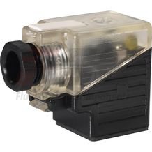
Based on the casting tolerances, with manifold installation, a manifold with an inside micrometer of 55 mm is to be used.Mating connectors for valves with connector “K4”, without circuitry, standard
3P Z4

Mating connectors for valves with connector “K4”, without circuitry, standard
3P Z4
For valves with connector “K4” according to EN 175301-803 and ISO 4400, 2-pole + PE, “large cubic connector” Mating connectors for valves with one or two solenoids (individual connection)Data sheet
Spare parts & repair
Mating connectors for valves with connector “K4”, with indicator light
3P Z5L
Mating connectors for valves with connector “K4”, with indicator light
3P Z5L
For valves with connector “K4” according to EN 175301-803 and ISO 4400, 2-pole + PE, “large cubic connector” Mating connectors for valves with one or two solenoids (individual connection)Data sheet
Spare parts & repair
Mating connectors for valves with connector “K4”, with indicator light and Zener diode suppression circuit
3P Z5L1
Mating connectors for valves with connector “K4”, with indicator light and Zener diode suppression circuit
3P Z5L1
For valves with connector “K4” according to EN 175301-803 and ISO 4400, 2-pole + PE, “large cubic connector” Mating connectors for valves with one or two solenoids (individual connection)Data sheet
Spare parts & repair
Mating connectors for valves with connector “K4”, with rectifier
3P RZ5
Mating connectors for valves with connector “K4”, with rectifier
3P RZ5
For valves with connector “K4” according to EN 175301-803 and ISO 4400, 2-pole + PE, “large cubic connector” Mating connectors for valves with one or two solenoids (individual connection)Data sheet
Spare parts & repair