

BOSCH REXROTH
R902269716
$5,876.00 USD
- BOSCH REXROTH
- Material:R902269716
- Model:A2FEM056/70NWVP2Z611C0J-0
Due to extremely high demand, please call 920-337-0234 for availability
The Bosch Rexroth A2FEM056/70NWVP2Z611C0J-0 (R902269716) is a compact high-pressure motor renowned for its robust bent-axis technology, tailored to integrate seamlessly into mechanical gearboxes. This motor is designed to deliver very high power density and total efficiency, which makes it an ideal solution for applications requiring a reliable and efficient hydraulic power source. Its size is optimized for space-saving due to the recessed mounting flange, making it suitable for environments where space is at a premium. With nominal pressure capabilities up to 400 bar and maximum pressure reaching up to 450 bar, the A2FEM056/70NWVP2Z611C0J-0 caters to a wide range of customer requirements and applications. The motor's high starting efficiency is particularly beneficial in applications that demand quick and responsive starts. Additionally, the option of an integrated flushing valve extends the potential uses of this motor by allowing for better heat dissipation and contamination control within hydraulic systems. The bent-axis design not only contributes to the motor's compactness but also enhances its durability, ensuring that it can withstand the rigors of demanding operational conditions. Whether used in open or closed circuits, this model from Bosch Rexroth stands out as a high-performance component in hydraulic systems requiring precise control and longevity.

| 1) | Only available for A2FEN |
| 2) | Not available for A2FEH |
| 3) | Not available for A2FEN |

| 1) | Not available for A2FEH |
Table of values
|
Size |
56 | 63 | 80 | 90 | 107 | 45 | 56 | 63 | 80 | 90 | 45 | 56 | 63 | 80 | 90 | |||
|
Version |
A2FEN | A2FEM | A2FEH | |||||||||||||||
|
Displacement |
Vg |
cm³ |
56.6 | 63 | 81.7 | 90.5 | 108.8 | 44.9 | 56.6 | 63 | 79.8 | 90.5 | 44.9 | 56.6 | 63 | 79.8 | 90.5 | |
|
Nominal pressure |
pnom |
bar |
300 | 300 | 300 | 300 | 300 | 400 | 400 | 400 | 400 | 400 | 450 | 450 | 450 | 450 | 450 | |
|
Maximum pressure |
pmax |
bar |
350 | 350 | 350 | 350 | 350 | 450 | 450 | 450 | 450 | 450 | 500 | 500 | 500 | 500 | 500 | |
|
Maximum speed |
nnom 1) |
rpm |
3750 | 3750 | 3375 | 3375 | 3000 | 5000 | 5000 | 5000 | 4500 | 4500 | 5000 | 5000 | 5000 | 4500 | 4500 | |
|
nmax 2) |
rpm |
4125 | 4125 | 3700 | 3700 | 3300 | 5500 | 5500 | 5500 | 5000 | 5000 | 5500 | 5500 | 5500 | 5000 | 5000 | ||
|
Inlet flow |
at nnom |
qV |
l/min |
212 | 236 | 276 | 305 | 326 | 225 | 283 | 315 | 359 | 407 | 225 | 283 | 315 | 359 | 407 |
|
Torque 3) |
at pnom |
M |
Nm |
270 | 301 | 390 | 432 | 519 | 286 | 360 | 401 | 508 | 576 | 322 | 405 | 451 | 571 | 648 |
|
Rotary stiffness |
c |
kNm/rad |
6.83 | 8.09 | 7.94 | 9.84 | 10.9 | 4.52 | 6.83 | 8.09 | 9.09 | 9.84 | 4.52 | 6.83 | 8.09 | 9.09 | 9.84 | |
|
Moment of inertia for rotary group |
JTW |
kg·m² |
0.0032 | 0.0032 | 0.0034 | 0.0054 | 0.0061 | 0.0032 | 0.0032 | 0.0032 | 0.0058 | 0.0054 | 0.0032 | 0.0032 | 0.0032 | 0.0058 | 0.0054 | |
|
Maximum angular acceleration |
ɑ |
rad/s² |
10000 | 12200 | 19800 | 4500 | 6000 | 5400 | 9000 | 11100 | 4500 | 4500 | 5000 | 8550 | 10500 | 4500 | 4500 | |
|
Case volume |
V |
l |
0.6 | 0.6 | 0.6 | 0.65 | 0.65 | 0.6 | 0.6 | 0.6 | 0.65 | 0.65 | 0.6 | 0.6 | 0.6 | 0.65 | 0.65 | |
|
Weight (approx.) |
m |
kg |
17 | 17 | 17 | 23 | 23 | 17 | 17 | 17 | 23 | 23 | 17 | 17 | 17 | 23 | 23 | |
| 1) |
These values are valid at: - for the optimum viscosity range from vopt = 36 to 16 mm2/s - with hydraulic fluid based on mineral oils |
| 2) | Intermittent maximum speed: overspeed for unload and overhauling processest, t < 5 s and Δp < 150 bar |
| 3) | Torque without radial force, with radial force see table "Permissible radial and axial forces of the drive shafts" |
Note
The values in the table are theoretical values, without consideration of efficiencies and tolerances. The values are rounded. Exceeding the maximum or falling below the minimum permissible values can lead to a loss of function, a reduction in operational service life or total destruction of the axial piston unit. Other permissible limit values, such as speed variation, reduced angular acceleration as a function of the frequency and the permissible angular acceleration at start (lower than the maximum angular acceleration) can be found in data sheet 90261.Speed range
No limit to minimum speed nmin. If uniformity of motion is required, speed nmin must not be less than 50 rpm.
|
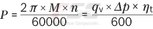
Determining the operating characteristics |
||
|
Inlet flow |

|
[l/min] |
|
Rotational speed |

|
[rpm] |
|
Torque |

|
[Nm] |
|
Power |
|
[kW] |
|
Key |
|
|
Vg |
Displacement per revolution [cm3] |
|
Δp |
Differential pressure [bar] |
|
n |
Rotational speed [rpm] |
|
ηv |
Volumetric efficiency |
|
ηhm |
Hydraulic-mechanical efficiency |
|
ηt |
Total efficiency (ηt = ηv • ηhm) |
Hydraulic fluids
The axial piston unit is designed for operation with mineral oil HLP according to DIN 51524.
Application instructions and requirements for hydraulic fluids should be taken from the following data sheets before the start of project planning:
90220: Hydraulic fluids based on mineral oils and related hydrocarbons
90221: Environmentally acceptable hydraulic fluids
90222: Fire-resistant, water-free hydraulic fluids (HFDR, HFDU)
90223: Fire-resistant, water-containing hydraulic fluids (HFAE, HFAS, HFB, HFC)
The axial piston unit is not suitable for operation with HFA hydraulic fluid.
Viscosity and temperature of hydraulic fluids
|
|
Viscosity |
Shaft |
Temperature1) |
Comment |
|
Cold start |
νmax ≤ 1600 mm²/s |
NBR2) |
ϑSt ≥ -40 °C |
t ≤ 3 min, without load (p ≤ 50 bar), n ≤ 1000 rpm, |
|
FKM |
ϑSt ≥ -25 °C |
|||
|
Warm-up phase |
ν = 400 … 1600 mm²/s |
|
t ≤ 15 min, p ≤ 0.7 • pnom and n ≤ 0.5 • nnom |
|
|
Continuous operation |
ν = 10 … 400 mm²/s3) |
NBR2) |
ϑ ≤ +78 °C |
measured at port T |
|
FKM |
ϑ ≤ +103 °C |
|||
|
νopt = 16 … 36 mm²/s |
range of optimum operating viscosity and efficiency |
|||
|
Short-term operation |
νmin = 7 … 10 mm²/s |
NBR2) |
ϑ ≤ +78 °C |
t ≤ 3 min, p ≤ 0.3 • pnom measured at port T |
|
FKM |
ϑ ≤ +103 °C |
| 1) | If the specified temperatures cannot be maintained due to extreme operating parameters, please contact us. |
| 2) | Special version, please contact us. |
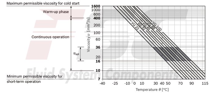
| 3) | Equates e.g. with the VG 46 a temperature range of +5 °C to +85 °C (see selection diagram) |
Note
To reduce high temperature of the hydraulic fluid in the axial piston unit we recommend the use of a flushing and boost pressure valve (see chapter Extended functions and versions).
Explanatory note regarding the selection of hydraulic fluid
The hydraulic fluid should be selected such that the operating viscosity in the operating temperature range is within the optimum range (vopt see selection diagram).
Selection diagram
Filtration of the hydraulic fluid
Finer filtration improves the cleanliness level of the hydraulic fluid, which increases the service life of the axial piston unit.
A cleanliness level of at least 20/18/15 is to be maintained according to ISO 4406.
At a hydraulic fluid viscosity of less than 10 mm²/s (e.g. due to high temperatures in short-term operation) at the drain port, a cleanliness level of at least 19/17/14 according to ISO 4406 is required.
For example, the viscosity is 10 mm²/s at:
HLP 32 a temperature of 73°C HLP 46 a temperature of 85°COperating pressure range
|
Pressure at working port A or B (high-pressure side) |
Definition |
||
|
Nominal pressure |
pnom |
see table of values |
The nominal pressure corresponds to the maximum design pressure. |
|
Maximum pressure |
pmax |
see table of values |
The maximum pressure corresponds to the maximum operating pressure within the single operating period. The sum of the single operating periods must not exceed the total operating period. |
|
Single operating period |
10 s |
||
|
Total operating period |
300 h |
||
|
Minimum pressure |
pHP min |
25 bar |
Minimum pressure on high-pressure side (port A or B) required to prevent damage to the axial piston unit. |
|
Minimum pressure at inlet (pump operating mode) |
pE min |
see diagram |
To prevent damage to the axial piston motor in pump mode (change of high-pressure side with unchanged direction of rotation, e.g. when braking),a minimum pressure must be guaranteed at the working port (inlet). The minimum pressure depends on the rotational speed and displacement of the axial piston unit. |
|
Total pressure |
pSu |
700 bar |
The summation pressure is the sum of the pressures at both work ports (A and B). |
|
Rate of pressure change |
Definition |
||
|
with integrated pressure relief valve |
RA max |
9000 bar/s |
Maximum permissible rate of pressure build-up and reduction during a pressure change over the entire pressure range. |
|
without pressure relief valve |
RA max |
16000 bar/s |
|
|
Case pressure at port T |
Definition |
||
|
Continuous differential pressure |
ΔpT cont |
2 bar |
Maximum averaged differential pressure at the shaft seal (case to ambient) |
|
Pressure peaks |
pT peak |
10 bar |
t < 0.1 s |
Note
Working pressure range valid when using hydraulic fluids based on mineral oils. Values for other hydraulic fluids, please contact us.Minimum pressure at inlet (pump operating mode)
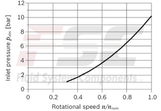
This diagram is only valid for the optimum viscosity range of vopt = 16 to 36 mm2/s
Please contact us if these conditions cannot be satisfied.
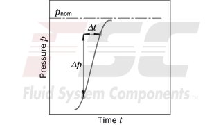
Pressure definition
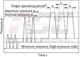
| 1) | Total operating period = t1 + t2 + ... + tn |
Rate of pressure change
Note
The service life of the shaft seal is influenced by the speed of the axial piston unit and the case pressure. The service life decreases with an increase of the mean differential pressure between the case and the ambient pressure and with a higher frequency of pressure spikes. The case pressure must be equal to or higher than the ambient pressure.Direction of flow
|
Direction of rotation, viewed on drive shaft |
|
|
clockwise |
counter-clockwise |
|
A to B |
B to A |
Permissible radial and axial forces of the drive shaft
|
Size |
56 | 63 | 80 | 90 | 107 | 45 | 56 | 63 | 80 | 90 | 45 | 56 | 63 | 80 | 90 | |||||||
|
Version |
A2FEN | A2FEM | A2FEH | |||||||||||||||||||
|
Drive shaft |
Code |
Z6 | Z8 | Z8 | Z8 | Z9 | Z9 | Z6 | Z6 | Z8 | Z8 | Z8 | Z9 | Z9 | Z6 | Z8 | Z8 | Z8 | Z9 | Z9 | ||
|
⌀ |
mm |
30 | 35 | 35 | 35 | 40 | 40 | 30 | 30 | 35 | 35 | 35 | 40 | 40 | 30 | 35 | 35 | 35 | 40 | 40 | ||
|
Maximum radial force |

|
Fq max |
7.1 kN | 6.1 kN | 6.9 kN | 8.7 kN | 8.6 kN | 10.4 kN | 7.6 kN | 9.5 N | 8.1 N | 9.2 N | 11.6 N | 10.2 N | 11.5 N | 8.6 N | 9.2 N | 10.3 N | 13.1 N | 10.2 N | 11.5 N | |
|
a |
mm |
18 | 18 | 18 | 18 | 20 | 20 | 18 | 18 | 18 | 18 | 20 | 20 | 20 | 18 | 18 | 18 | 20 | 20 | 20 | ||
|
Permitted torque at Fq max |
Tq max |
Nm |
270 | 270 | 301 | 390 | 432 | 519 | 286 | 360 | 360 | 401 | 508 | 508 | 576 | 322 | 405 | 451 | 571 | 571 | 645 | |
|
Permitted differential pressure at Fq max |
Δpq max |
bar |
300 | 300 | 300 | 300 | 300 | 300 | 400 | 400 | 400 | 400 | 400 | 400 | 400 | 450 | 450 | 450 | 450 | 450 | 450 | |
|
Maximum axial force, when standstill or in non-pressurized conditions |

|
+ Fax max |
N |
0 | 0 | 0 | 0 | 0 | 0 | 0 | 0 | 0 | 0 | 0 | 0 | 0 | 0 | 0 | 0 | 0 | 0 | 0 |
|
- Fax max |
N |
800 | 800 | 800 | 800 | 1000 | 1000 | 800 | 800 | 800 | 800 | 1000 | 1000 | 1000 | 800 | 800 | 800 | 1000 | 1000 | 1000 | ||
|
Maximum axial force, per bar operating pressure |
+ Fax max |
N/bar |
8.7 | 8.7 | 8.7 | 8.7 | 10.6 | 10.6 | 8.7 | 8.7 | 8.7 | 8.7 | 10.6 | 10.6 | 10.6 | 8.7 | 8.7 | 8.7 | 10.6 | 10.6 | 10.6 | |
General notes
The values given are maximum values and do not apply to continuous operation. The axial force in direction -Fax is to be avoided as the lifetime of the bearing is reduced. Special requirements apply in the case of belt drives. Please contact us.Effect of radial force Fq on the service life of bearings
By selecting a suitable direction of radial force Fq the load on the bearings caused by the internal rotary group forces can be reduced, thus optimizing the service life of the bearings. Recommended position of mating gear is dependent on direction of rotation. Examples:
Toothed gear drive

|
1 |
Direction of rotation "counter-clockwise", pressure at port B |
|
2 |
Direction of rotation "clockwise", pressure at port A |
|
3 |
Direction of rotation "bidirectional" |
Port plate 11
SAE working ports at bottom

| 1) | To shaft collar |
| 2) | The O-ring is not included in the delivery contents. |
|
Version |
Size |
D1 |
D2 |
D3 |
D4 |
D7 |
D8 |
D10 |
D11 |
D12 |
D14 |
D15 |
D16 |
D17 |
D18 |
D19 |
D20 |
D28 |
D29 |
D31 |
D33 |
D40 |
D41 |
D42 |
D46 |
D47 |
O-ring |
|
|
mm |
mm |
mm |
mm |
mm |
mm |
mm |
mm |
mm |
mm |
mm |
mm |
mm |
mm |
mm |
mm |
mm |
mm |
mm |
mm |
mm |
mm |
mm |
mm |
mm |
mm |
mm |
||
| A2FEN | 56 | 160 | - 0.025 | 118 | 112.4 | 122 | 235 | 18 | 92.3 | 90 | 86 | 125 | 88.4 | 10 | 30 | 65.9 | 121.5 | 32.9 | 200 | 18 | 5.2 | 147 | 23.8 | 50.8 | 19 | 75 | 20 | Ø150 × 4 |
| 63 | 160 | - 0.025 | 118 | 112.4 | 122 | 235 | 18 | 92.3 | 90 | 86 | 125 | 88.4 | 10 | 30 | 65.9 | 121.5 | 32.9 | 200 | 18 | 5.2 | 147 | 23.8 | 50.8 | 19 | 75 | 20 | Ø150 × 4 | |
| 80 | 160 | - 0.025 | 118 | 112.4 | 122 | 235 | 18 | 92.3 | 90 | 86 | 125 | 88.4 | 10 | 30 | 65.9 | 121.5 | 32.9 | 200 | 18 | 5.2 | 147 | 23.8 | 50.8 | 19 | 75 | 20 | Ø150 × 4 | |
| 90 | 190 | - 0.029 | 140.3 | 120.5 | 142 | 260 | 20 | 110 | 106 | 101.5 | 145 | 93.5 | 10 | 30 | 67.5 | 127 | 33 | 224 | 22 | 5.2 | 165 | 27.8 | 57.2 | 25 | 84 | 25 | Ø182 × 4 | |
| 107 | 190 | - 0.029 | 140.3 | 120.5 | 142 | 260 | 20 | 110 | 106 | 101.5 | 145 | 93.5 | 10 | 30 | 67.5 | 127 | 33 | 224 | 22 | 5.2 | 165 | 27.8 | 57.2 | 25 | 84 | 25 | Ø182 × 4 | |
| A2FEM | 45 | 160 | - 0.025 | 118 | 112.4 | 122 | 235 | 18 | 92.3 | 90 | 86 | 125 | 88.4 | 10 | 30 | 65.9 | 121.5 | 32.9 | 200 | 18 | 5.2 | 147 | 23.8 | 50.8 | 19 | 75 | 20 | Ø150 × 4 |
| 56 | 160 | - 0.025 | 118 | 112.4 | 122 | 235 | 18 | 92.3 | 90 | 86 | 125 | 88.4 | 10 | 30 | 65.9 | 121.5 | 32.9 | 200 | 18 | 5.2 | 147 | 23.8 | 50.8 | 19 | 75 | 20 | Ø150 × 4 | |
| 63 | 160 | - 0.025 | 118 | 112.4 | 122 | 235 | 18 | 92.3 | 90 | 86 | 125 | 88.4 | 10 | 30 | 65.9 | 121.5 | 32.9 | 200 | 18 | 5.2 | 147 | 23.8 | 50.8 | 19 | 75 | 20 | Ø150 × 4 | |
| 80 | 190 | - 0.029 | 140.3 | 120.5 | 142 | 260 | 20 | 110 | 106 | 101.5 | 145 | 93.5 | 10 | 30 | 67.5 | 127 | 33 | 224 | 22 | 5.2 | 165 | 27.8 | 57.2 | 25 | 84 | 25 | Ø182 × 4 | |
| 90 | 190 | - 0.029 | 140.3 | 120.5 | 142 | 260 | 20 | 110 | 106 | 101.5 | 145 | 93.5 | 10 | 30 | 67.5 | 127 | 33 | 224 | 22 | 5.2 | 165 | 27.8 | 57.2 | 25 | 84 | 25 | Ø182 × 4 | |
| A2FEH | 45 | 160 | - 0.025 | 118 | 112.4 | 122 | 235 | 18 | 92.3 | 90 | 86 | 125 | 88.4 | 10 | 30 | 65.9 | 121.5 | 32.9 | 200 | 18 | 5.2 | 147 | 23.8 | 50.8 | 19 | 75 | 20 | Ø150 × 4 |
| 56 | 160 | - 0.025 | 118 | 112.4 | 122 | 235 | 18 | 92.3 | 90 | 86 | 125 | 88.4 | 10 | 30 | 65.9 | 121.5 | 32.9 | 200 | 18 | 5.2 | 147 | 23.8 | 50.8 | 19 | 75 | 20 | Ø150 × 4 | |
| 63 | 160 | - 0.025 | 118 | 112.4 | 122 | 235 | 18 | 92.3 | 90 | 86 | 125 | 88.4 | 10 | 30 | 65.9 | 121.5 | 32.9 | 200 | 18 | 5.2 | 147 | 23.8 | 50.8 | 19 | 75 | 20 | Ø150 × 4 | |
| 80 | 190 | - 0.029 | 140.3 | 120.5 | 142 | 260 | 20 | 110 | 106 | 101.5 | 145 | 93.5 | 10 | 30 | 67.5 | 127 | 33 | 224 | 22 | 5.2 | 165 | 27.8 | 57.2 | 25 | 84 | 25 | Ø182 × 4 | |
| 90 | 190 | - 0.029 | 140.3 | 120.5 | 142 | 260 | 20 | 110 | 106 | 101.5 | 145 | 93.5 | 10 | 30 | 67.5 | 127 | 33 | 224 | 22 | 5.2 | 165 | 27.8 | 57.2 | 25 | 84 | 25 | Ø182 × 4 | |
Port plate 02
SAE working ports at side, opposite

| 1) | To shaft collar |
| 2) | The O-ring is not included in the delivery contents. |
|
Version |
Size |
D1 |
D2 |
D3 |
D4 |
D7 |
D8 |
D10 |
D11 |
D12 |
D14 |
D15 |
D16 |
D17 |
D18 |
D19 |
D20 |
D28 |
D29 |
D31 |
D33 |
D40 |
D41 |
D42 |
D46 |
D47 |
O-ring |
|
|
mm |
mm |
mm |
mm |
mm |
mm |
mm |
mm |
mm |
mm |
mm |
mm |
mm |
mm |
mm |
mm |
mm |
mm |
mm |
mm |
mm |
mm |
mm |
mm |
mm |
mm |
mm |
||
| A2FEN | 56 | 160 | - 0.025 | 118 | 112.4 | 127.5 | 235 | 18 | 92.3 | 90 | 86 | 125 | 88.4 | 10 | 30 | 65.9 | 123 | 32.9 | 200 | 18 | 5.2 | 141 | 23.8 | 50.8 | 19 | 75 | 20 | Ø150 × 4 |
| 63 | 160 | - 0.025 | 118 | 112.4 | 127.5 | 235 | 18 | 92.3 | 90 | 86 | 125 | 88.4 | 10 | 30 | 65.9 | 123 | 32.9 | 200 | 18 | 5.2 | 141 | 23.8 | 50.8 | 19 | 75 | 20 | Ø150 × 4 | |
| 80 | 160 | - 0.025 | 118 | 112.4 | 127.5 | 235 | 18 | 92.3 | 90 | 86 | 125 | 88.4 | 10 | 30 | 65.9 | 123 | 32.9 | 200 | 18 | 5.2 | 141 | 23.8 | 50.8 | 19 | 75 | 20 | Ø150 × 4 | |
| 90 | 190 | - 0.029 | 140.3 | 120.5 | 148.5 | 260 | 20 | 110 | 106 | 101.5 | 145 | 93.5 | 10 | 30 | 67.5 | 127 | 33 | 224 | 22 | 5.2 | 159 | 27.8 | 57.2 | 25 | 84 | 25 | Ø182 × 4 | |
| 107 | 190 | - 0.029 | 140.3 | 120.5 | 148.5 | 260 | 20 | 110 | 106 | 101.5 | 145 | 93.5 | 10 | 30 | 67.5 | 127 | 33 | 224 | 22 | 5.2 | 159 | 27.8 | 57.2 | 25 | 84 | 25 | Ø182 × 4 | |
| A2FEM | 45 | 160 | - 0.025 | 118 | 112.4 | 127.5 | 235 | 18 | 92.3 | 90 | 86 | 125 | 88.4 | 10 | 30 | 65.9 | 123 | 32.9 | 200 | 18 | 5.2 | 141 | 23.8 | 50.8 | 19 | 75 | 20 | Ø150 × 4 |
| 56 | 160 | - 0.025 | 118 | 112.4 | 127.5 | 235 | 18 | 92.3 | 90 | 86 | 125 | 88.4 | 10 | 30 | 65.9 | 123 | 32.9 | 200 | 18 | 5.2 | 141 | 23.8 | 50.8 | 19 | 75 | 20 | Ø150 × 4 | |
| 63 | 160 | - 0.025 | 118 | 112.4 | 127.5 | 235 | 18 | 92.3 | 90 | 86 | 125 | 88.4 | 10 | 30 | 65.9 | 123 | 32.9 | 200 | 18 | 5.2 | 141 | 23.8 | 50.8 | 19 | 75 | 20 | Ø150 × 4 | |
| 80 | 190 | - 0.029 | 140.3 | 120.5 | 148.5 | 260 | 20 | 110 | 106 | 101.5 | 145 | 93.5 | 10 | 30 | 67.5 | 127 | 33 | 224 | 22 | 5.2 | 159 | 27.8 | 57.2 | 25 | 84 | 25 | Ø182 × 4 | |
| 90 | 190 | - 0.029 | 140.3 | 120.5 | 148.5 | 260 | 20 | 110 | 106 | 101.5 | 145 | 93.5 | 10 | 30 | 67.5 | 127 | 33 | 224 | 22 | 5.2 | 159 | 27.8 | 57.2 | 25 | 84 | 25 | Ø182 × 4 | |
| A2FEH | 45 | 160 | - 0.025 | 118 | 112.4 | 127.5 | 235 | 18 | 92.3 | 90 | 86 | 125 | 88.4 | 10 | 30 | 65.9 | 123 | 32.9 | 200 | 18 | 5.2 | 141 | 23.8 | 50.8 | 19 | 75 | 20 | Ø150 × 4 |
| 56 | 160 | - 0.025 | 118 | 112.4 | 127.5 | 235 | 18 | 92.3 | 90 | 86 | 125 | 88.4 | 10 | 30 | 65.9 | 123 | 32.9 | 200 | 18 | 5.2 | 141 | 23.8 | 50.8 | 19 | 75 | 20 | Ø150 × 4 | |
| 63 | 160 | - 0.025 | 118 | 112.4 | 127.5 | 235 | 18 | 92.3 | 90 | 86 | 125 | 88.4 | 10 | 30 | 65.9 | 123 | 32.9 | 200 | 18 | 5.2 | 141 | 23.8 | 50.8 | 19 | 75 | 20 | Ø150 × 4 | |
| 80 | 190 | - 0.029 | 140.3 | 120.5 | 148.5 | 260 | 20 | 110 | 106 | 101.5 | 145 | 93.5 | 10 | 30 | 67.5 | 127 | 33 | 224 | 22 | 5.2 | 159 | 27.8 | 57.2 | 25 | 84 | 25 | Ø182 × 4 | |
| 90 | 190 | - 0.029 | 140.3 | 120.5 | 148.5 | 260 | 20 | 110 | 106 | 101.5 | 145 | 93.5 | 10 | 30 | 67.5 | 127 | 33 | 224 | 22 | 5.2 | 159 | 27.8 | 57.2 | 25 | 84 | 25 | Ø182 × 4 | |
Drive shafts
Overview of available drive shafts
A2FEN
|
Size |
56 | 63 | 80 | 90 | 107 | |||
|
Drive shafts |
Code |
Z6 | Z8 | Z8 | Z8 | Z9 | Z9 | |
A2FEM
|
Size |
45 | 56 | 63 | 80 | 90 | ||||
|
Drive shafts |
Code |
Z6 | Z6 | Z8 | Z8 | Z8 | Z9 | Z9 | |
A2FEH
|
Size |
45 | 56 | 63 | 80 | 90 | |||
|
Drive shafts |
Code |
Z6 | Z8 | Z8 | Z8 | Z9 | Z9 | |
Splined shaft DIN 5480

| 1) | Center bore according to DIN 332 (thread according to DIN 13) |
| 2) | For size 80, pressure range "M" and "H": ⌀45 mm |
Ports
|
Size |
56 | 63 | 80 | 90 | 107 | 45 | 56 | 63 | 80 | 90 | 45 | 56 | 63 | 80 | 90 | ||
|
Version |
A2FEN | A2FEM | A2FEH | ||||||||||||||
|
A, B |
Working port |
Size |
3/4 in | 1 in | 3/4 in | 1 in | 3/4 in | 1 in | |||||||||
|
Standard |
Dimensions according to SAE J518 | ||||||||||||||||
|
Fastening thread |
M10 × 1,5; 17 mm deep | M12 × 1,75; 17 mm deep | M10 × 1,5; 17 mm deep | M12 × 1,75; 17 mm deep | M10 × 1,5; 17 mm deep | M12 × 1,75; 17 mm deep | |||||||||||
|
State on delivery |
With protective cover (must be connected) | ||||||||||||||||
|
T1 |
Drain port |
Size |
M18 × 1,5; 12 mm deep | ||||||||||||||
|
Standard 1) |
DIN 3852 | ||||||||||||||||
|
State on delivery |
Plugged (observe installation instructions) | ||||||||||||||||
|
T2 |
Drain port |
Size |
M18 × 1,5; 12 mm deep | ||||||||||||||
|
Standard 1) |
DIN 3852 | ||||||||||||||||
|
State on delivery |
With protective cover (observe installation instructions) | ||||||||||||||||
| 1) | The spot face can be deeper than specified in the appropriate standard. |
Flushing and boost pressure valve
The integrated flushing and boost pressure valve is used in closed circuits for the removal of heat and to ensure a minimum boost pressure level.
Hydraulic fluid is directed from the respective low pressure side into the motor housing. This is then fed into the reservoir, together with the leakage. The removed hydraulic fluid must be replaced by cooled hydraulic fluid from the boost pump.
Cracking pressure of pressure retaining valve
(observe when setting the primary valve)
fixed setting: 16 bar
Switching pressure of flushing piston Δp
8±1 bar
Circuit diagram

Flushing flow qv
Orifices can be used to adjust the flushing flows as required. The following information is based on:
ΔpND = pND – pG = 25 bar und ν = 10 mm2/s
(pND = low pressure, pG = case pressure)
|
Size |
Flushing flow qv |
Orifice-⌀ |
|
l/min |
mm |
|
|
all |
2.6 |
1.0 |
|
6 |
1.5 |
|
|
7.4 |
1.7 |
|
|
8,5 |
1.8 |
|
|
11.4 |
2.3 |
|
|
12.5 |
3 |
Speed sensor DSA
The speed sensor DSA scans contactless a specific spline on the rotary group and thus generates an output signal with constant amplitude and a frequency proportional to the motor speed. In addition to the speed also the direction of rotation is detected. The sensor is mounted on the port provided for this purpose with one mounting bolt.
The version A2F...A ("prepared for speed sensor", i.e. without sensor) is equipped with the splines on the rotary group needed for future speed measurement. On deliveries without sensor, the port is plugged with a pressure-resistant cover.
Technical data and further specifications of the sensor DSA can be found in the relevant data sheet 95133.
We recommend ordering the fixed motor A2F complete with mounted sensor.
Ports Metric version (code N)

|
Motor |
Number of teeth |
N1 |
N3 |
N4 |
|
|
Version |
Size |
mm |
mm |
mm |
|
| A2FEN | 56 … 80 | 47 | 32 | 36.3 | 54.6 |
| 90 … 107 | 53 | 32 | 30.4 | 58.8 | |
|
A2FEM A2FEH |
45 … 63 | 47 | 32 | 36.3 | 54.6 |
| 80 … 90 | 53 | 32 | 30.4 | 58.8 | |
Installation instructions
General
During commissioning and operation, the axial piston unit must be filled with hydraulic fluid and air bled. This must also be observed following a relatively long standstill as the axial piston unit may drain back to the reservoir via the hydraulic lines. The case drain fluid in the housing must be directed to the reservoir via the highest available drain port (T1,T2). If a shared drain line is used for several units, make sure that the respective case pressure is not exceeded. The shared drain line must be dimensioned to ensure that the maximum permissible case pressure of all connected units is not exceeded in any operating conditions, specifically on cold start. If this is not possible, separate reservoir lines must be laid as required. To achieve favorable noise values, all connecting lines should be decoupled by using elastic elements and above-reservoir installation is to be avoided. In all operating conditions, the drain line must flow into the reservoir below the minimum fluid level.
Note
The “shaft upwards” installation position is not permissible..
Installation position
See the following examples 1 to 6.
Further installation positions are possible upon request. Recommended installation position: 1 and 2.
Below-tank installation (standard)
Below-tank installation is at hand if the axial piston unit is installed below the minimum liquid level outside the tank.

|
Installation position |
Air bleeding |
Filling |
|
1 |
‒ |
T1 |
|
2 |
‒ |
T2 |
|
3 |
‒ |
T1 |
Above-reservoir installation
Above-reservoir installation means that the axial piston unit is installed above the minimum fluid level of the reservoir.

|
Installation position |
Air bleeding |
Filling |
|
4 |
F |
T1 (F) |
|
5 |
F |
T2 (F) |
|
6 |
F |
T1 (F) |
|
Key |
|
|
F |
Filling / Air bleeding |
|
T1, T2 |
Drain port |
|
ht min |
Minimum required immersion depth (200 mm) |
|
hmin |
Minimum required spacing to reservoir bottom (100 mm) |
Note
Connection F is part of the external piping and must be provided on the customer side to simplify the filling and bleeding.General project planning notes
The axial piston unit is designed to be used in open and closed circuits. The project planning, installation and commissioning of the axial piston unit require the involvement of qualified skilled personnel. Before using the axial piston unit, please read the corresponding instruction manual completely and thoroughly. If necessary, request it from Bosch Rexroth. Before finalizing your design, request a binding installation drawing. The specified datas and notes must be observed. Preservation: Our axial piston units are supplied as standard with preservative protection for a maximum of 12 months. If longer preservative protection is required (maximum 24 months), please specify this in plain text when placing your order. The preservation times are valid under optimal storage conditions. Details of these conditions can be found in the data sheet 90312 or the instruction manual. Not all versions of the product are approved for use in a safety function according to ISO 13849. Please consult the responsible contact person at Bosch Rexroth if you require reliability parameters (e.g. MTTFD) for functional safety. A pressure relief valve is to be provided in the hydraulic system. Observe the instructions in the instruction manual regarding tightening torques of connection threads and other threaded joints used. The notes in the instruction manual on tightening torques of the port threads and other screw joints must be observed. The ports and fastening threads are designed for the permissible maximum pressure pmax (see instruction manual). The machine or system manufacturer must ensure that the connecting elements and lines correspond to the specified operating conditions (pressure, flow, hydraulic fluid, temperature) with the necessary safety factors. The working ports and function ports are designated only to accommodate hydraulic lines.During and shortly after operation, there is a risk of burns on the axial piston unit. Take appropriate safety measures (e.g. by wearing protective clothing).