
HYDRAFORCE
5164061
$247.46 USD
- HYDRAFORCE
- Material:5164061
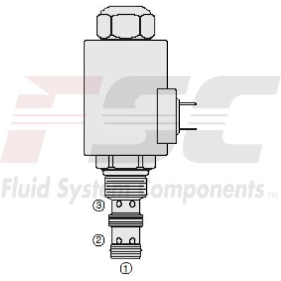
- Model:ZL70-30A-8T-N-00 FLOW CONTROL
- Summary:N.C. BIDIRECTIONAL FLOW REGULATOR U.S. PATENT No. 6,167,906
Due to extremely high demand, please call 920-337-0234 for availability
The Hydraforce 5164061 (5164061) is a high-performance hydraulic component designed for precise fluid control in complex hydraulic systems. This solenoid operated, pressure compensated, spool type valve is normally closed and offers proportional bidirectional flow control capabilities. It ensures regulated flow in both directions, either from port 2 to port 3 or vice versa, with port 1 being blocked. The flow regulation is directly proportional to the electric current applied to its solenoid, allowing for fine-tuned operations based on varying electrical inputs. Constructed with an aluminum body and featuring a hardened spool and cage, the 5164061 valve promises durability and a long operational life even under demanding conditions. It demonstrates excellent linearity and hysteresis characteristics which are crucial for maintaining stability and performance in fluid management systems. The valve is specifically designed to work with mineral-based or synthetic fluids that have lubricating properties, ensuring compatibility with a wide range of hydraulic media. Additionally, the 5164061 model offers flexibility through optional coil voltages and terminations, adapting to different system requirements. It also includes features like efficient wet-armature construction and an optional manual override, enhancing its functionality and ease of use in various application settings. With choices of two regulated flow ranges, it meets diverse application needs effectively. This model's specifications include a thread size of 7/8-14 UNF-2A and across flats measurements of 26.9 mm and 28.7 mm respectively, confirming its adaptability to standard hydraulic fittings.
Unit weight:
0.32 kg (0.70 lb)
ZL70-30X
0.37 kg (0.81 lb)
ZL70-30XM
0.45 kg (1.00 lb)
ZL70-30XG
Internal wetted surface area:
209.6 cm² (32.5 in²)
Zl7030x
212.8 cm² (33.0 in²)
Zl7030xm zl7030xg
| Ratings | Pressure Ratings Pressure rating: 241 bar (3500 psi) Inlet (port 1) 207 bar (3000 psi) Regulated (port 3) 207 bar (3000 psi) Bypass (port 2) Proof pressure: 689 bar (10000 psi) Burst pressure: 1103 bar (16000 psi) Flow Ratings Flow rating: 0 to 20.1 lpm (0 to 5.3 gpm) Flow range A 0 to 9.8 lpm (0 to 2.6 gpm) Flow range b Maximum internal leakage: 0.38 lpm (0.1 gpm) Max at 0 current Hysteresis flow: lpm (gpm) Maximum Temperature Ratings Operating fluid temperature: -40 to 100 °C (-40 to 212 °F) With buna N seals -26 to 204 °C (-15 to 400 °F) With fluorocarbon seals Storage temperature: -40 to 70 °C (-40 to 160 °F) Ambient temperature: -40 to 70 °C (-40 to 160 °F) |
| Operating Parameters | Fluids:
Mineral based or synthetic hydraulic fluid with lubricating properties Fluid viscosity range: 7.4 to 420 cSt Maximum operating contamination level: 18/16/13 per ISO 4406 |
| Electrical Parameters | Maximum control current:
1400 ±100 mA 12 V 70 Series D-coil 700 ±50 mA 24 V 70 Series D-coil 1400 ±100 mA 12 V 70 Series E-coil 700 ±50 mA 24 V 70 Series E-coil Threshold current: 250 ±100 mA 12 V 70 Series D-coil 125 ±50 mA 24 V 70 Series D-coil 250 ±100 mA 12 V 70 Series E-coil 125 ±50 mA 24 V 70 Series E-coil Valve inductance: 200 mH 12 V 70 Series D-coil 600 mH 24 V 70 Series D-coil 240 mH 12 V 70-Series E-coil 700 mH 24 V 70-Series E-coil Dither PWM frequency: 100 to 250 Hz |
| Performance |  |
| Installation Specifications | Cavity:
VC10-3 10-size-3-way Cavities Cartridge installation torque: 34 to 37 N-m (25 to 27 ft-lb) Coil nut torque: 14 to 16 N-m (10 to 12 ft-lb) Cover cap torque: 7 to 9 N-m (5 to 7 ft-lb) Orientation restriction: None |
| Order Code | POSITION CODE DESCRIPTION ZL70-30DE-H-J-L D Flow Range D A 0 to 21.1 lpm (0 to 5.3 gpm) Flow Range D B 0 to 9.8 lpm (0 to 2.6 gpm) Flow Range E Manual Override E BLANK NONE E G Variable Position Override, Red Knurled Knob with Cover Cap E M Variable Position Override, Red Knurled Knob H Line Body H 0 No Body H 6T Aluminum SAE 6 H 8T Aluminum SAE 8 H 6TD Ductile Iron SAE 6 H 8TD Ductile Iron SAE 8 H 3B Aluminum BSPP 3/8" (3) H 3BD Ductile Iron BSPP 3/8" (3) J Seal J N Buna-N J V Fluorocarbon J P Polyurethane J U PPDI Urethane L Coil L 0 No Coil L 12DG 12 VDC, D-Coil, DIN 43650 L 12DL 12 VDC, D-Coil, Dual Lead Wires L 12DL/W 12 VDC, D-Coil, Dual Lead Wires with Weatherpak L 12DS 12 VDC, D-Coil, Dual Spade L 12ER 12 VDC, E-Coil, Deutsch L 12EY 12 VDC, E-Coil, Metri-Pack 150 L 24DG 24 VDC, D-Coil, DIN 43650 L 24DL 24 VDC, D-Coil, Dual Lead Wires L 24DS 24 VDC, D-Coil, Dual Spade L 24ER 24 VDC, E-Coil, Deutsch |

Seal kit:
SK10-3X-MM
X = seal option
Seal kit installation instructions
Housings:
Available
10-3w valve bodies
Coils:
70 size D
coils
70 size E
coils
| Product ZIP File | Download Product ZIP File |
| Product PDF File | Download Product PDF File |