


BOSCH
0811405144
BOSCH
MATERIAL: 0811405144
MODEL: VT-SSPA1-508-2X/V0/0
Due to extremely high demand, please call 920-337-0234 for availability
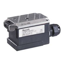
The amplifier is used to control proportional valves without electrical position control.
It is connected directly to the solenoid plug of the valve. The connection cable on the control side (UB, command value) is lead through a cable gland and connected.
An LED signals the available supply voltage. Depending on the type of the amplifier, the command value presetting is a voltage 0...10 V or a current 4...20 mA.
The command value can be adjusted with regard to zero point and sensitivity. With voltage presetting, a differential input is available.
In addition, the command value can be led over a ramp.
To allow for adjustment to special applications, the dither amplitude was designed variably.
Upon delivery, the dither amplitude has already been set to a perfect value so that another adjustment is only necessary in the above-mentioned special cases.
|
01 |
02 |
03 |
04 |
05 |
||||
|
VT-SSPA1 |
‒ |
508 |
‒ |
2X |
/ |
V0 |
/ |
|
01 |
Valve amplifiers for proportional valves without electrical position feedback, Analog, Connector design |
VT-SSPA1 |
|
02 |
For valves: |
525 |
|
03 |
Component series 20 ... 29 (20 ... 29: unchanged technical data and pin assignment) |
2X |
|
04 |
Version: standard |
V0 |
|
05 |
Voltage input 0...10 V |
0 |
|
Current input 4...20 mA |
I |
General
|
Component series |
2X | ||
|
Material number |
Data sheet |
1819929093 | |
|
Type of electronics |
Analog | ||
|
Design |
Plug-in connector |
Voltage supply
|
Operating voltage |
nominal |
U |
V |
24 |
|
Lower limit value |
UB(t)min |
V |
21 | |
|
Upper limit value |
UB(t)max |
V |
31 | |
|
Residual ripple |
uSS |
V |
< 2 | |
|
Power consumption |
max. |
Smax |
VA |
55 |
Analog inputs
|
Command value |
Voltage (differential input) |
U |
V |
0 ... 10 |
|
Current |
I |
mA |
4 … 20 |
Solenoid outputs
|
Solenoid current |
max. |
Imax |
A |
0.8 |
|
Setting range |
Dither frequency |
f |
95 ... 340 | |
|
Solenoid output |
other properties |
Rectangular voltage, pulse-modulated, short-circuit-proof |
Adjustment options
|
Zero point calibration information |
See characteristic curves | ||
|
Range sensitivity adjustment |
See characteristic curves | ||
|
Ramp time up/down |
t |
s |
0.06 … 5 |
Displays
|
LED display |
Green |
Operating voltage |
Supplementary information
|
Special features |
Fast energization for short actuating time, adjustments via potentiometer | |||
|
Standard connection |
of solenoid |
DIN 43650 | ||
|
Connection cross-section |
A |
5 x 0.75 mm2, shielded | ||
|
Anschlussart |
Cable gland and screw terminals | |||
|
Type of protection according to EN 60529 1) |
Extra für FN |
IP65 | ||
|
Electro-magnetic compatibility |
tested according to |
EN 61000-6-2: 2002-08, EN 61000-6-3: 2002-08 | ||
|
Ambient temperature range |
ϑ |
°C |
-20 … 70 | |
|
Storage temperature range |
ϑ |
°C |
-25 … 85 | |
|
Weight |
m |
kg |
0.23 | |
| 1) | In plugged condition |
For applications outside these parameters, please consult us!

|
P1 |
Ramp time |
|
P2 |
Sensitivity |
|
P3 |
Zero point |
|
P4 |
Dither frequency |
|
St1 |
Connection terminals |
|
LED |
Operating voltage display |

Dimensions in mm

The plug-in amplifier may only be unplugged and plugged when de-energized. The distance to aerial lines, radios and radar systems must be sufficient (> 1 m). Do not lay solenoid and signal lines near power cables. For signal lines and solenoid conductors, we recommend using shielded cables. The cable shield must be connected to the control cabinet extensively and as short as possible.
Preparation of the connection cable (“Preparation of the connection cable” graphic) Lead the cable through the cable gland and connect it to terminal St 1. Applying the supply voltage → LED (green) is illuminated. Zero point adjustment → poti P3 with minimum command value presetting (“Zero point and sensitivity” graphic) Sensitivity adjustment → poti P2 with maximum command value presetting (“Zero point and sensitivity” graphic) Dither frequency adjustment → poti P4 (“Dither frequency” graphic)
The dither frequency is already correctly adjusted when supplied. For special applications, a correction may be necessary. In this case, please contact DC-IA/PRM12. Ramp time adjustment → poti P1 (“Ramp time” graphic) 
Ramp time

Dither frequency

Zero point and sensitivity
